Principle
Technique 1: steel dam
A steel dam wall is a temporary dam construction, with or without anchorage or mine props. There are various techniques for placing a steel dam wall into the soil. Depending on the soil construction and boundary conditions from the surroundings (vibration and noise issues), the most common choice is pile-driving, vibration and/or compression, and possibly injection. The steel wall itself is water-tight, so long as it has not been damaged by corrosion. An important point in this technique is that the joints between the dam wall planks and the under-plank are sensitive to leakage in difficult to permeate layers. After the planks or boards have been placed, the joints are injected with bentonite-cement in order to further reduce leakage via the joints. The profile of the dam wall planks is U or Z-shaped. The construction can be fitted with anchorage or mine props.
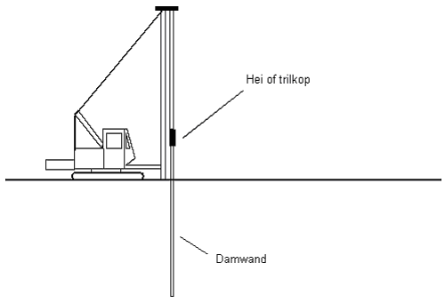
Figure: Diagram of steel dam wall
Technique 2: Deep wall
A deep wall is a permanent dam construction, with or without anchorage or stamping. Deep walls are created by digging a small (0.40 to 1.20 m wide) and relatively deep trench and filling it with a substance that is difficult to permeate. The substances that are normally used consist of bentonite and cement, to which fillers can be added if desired. Substances like concrete and plastic concrete are also used. A foil screen can also be used for a deep wall. Kelly-grips can, for example, be implemented while digging the trenches. The grips are fixed to a long and reasonably strong rod. Other digging activities are required for deep trenches; the use of a hyrdo-digger, for example. Fixed to a strong metal frame, blades turn in opposite directions and help to loosen the ground. This machine is able to dig small and much deeper trenches in just about every type of ground.
During the construction of cement-bentonite deep walls, 1-phase as well as 2-phase systems are used. A 1-phase system involves the use of a cement-bentonite suspension. This suspension permits one to cure after a section of the trench has been prepared. In a 2-phase system, first a bentonite rinse is used and, after digging for a section has been completed, this support fluid is replaced by the substance which will form the definitive wall. The support fluid is replaced, by discharging it via disposal chutes underneath the trench, by the heavier mix. The support fluid can be used again once it has been regenerated
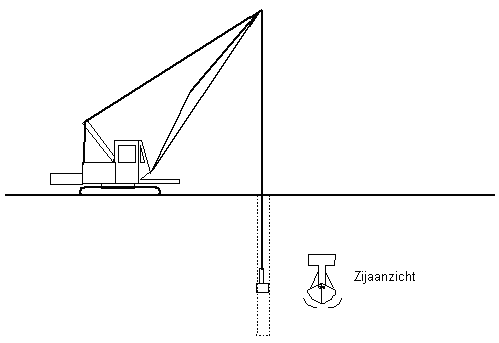
Figure: Deep wall Diagram
Technique 3: Cement-bentonite wall
By placing a screen wall or a screen/foil wall combination, one can form a water-inhibiting or water-dam wall. By using a crane with a rig, a special injection-plank is vibrated or pile-driven into the soil. When the screen is being removed, a water-inhibiting material is dosed (bentonite/cement, P.U.). The screen (injection wall) has a thickness of 10 to 25 cm and has water-inhibiting properties. At the same time as an injection plank, a synthetic screen can also be vibrated or injected into the soil, up to the required depth. A second injection plank with a synthetic screen can also be joined to the first plank, and can be placed into the soil in the same manner. The screens must be joined with an inter-locking joint. When the second injection plank is deep enough, the first injection plank is disconnected from its screening material and is vibrated out of the soil.
The cycle is repeated hereafter. The width of the screen sections varies between 1 and 2.50 metres. The screen sections with foil are joined to each other with locking-joints. The connection to the sealing layer is an important factor.. Finishing off with injection or grouting will often be required. The installed screen is water-dam. An alternative method which is less implemented is the placement of a foil screen via a ‘chain excavator’. During excavation, the vertically upright roll is placed inside, which creates a continuous water-tight screen.
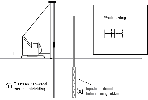
Figure: Diagram of cement-bentonite wall
Implementation area and implementation conditions
When assessing the compatibility of insulation materials, in addition to the technical realisation possibilities, the implementation conditions also play a role.
The following technical realisation possibilities should be considered:
- Steel dam walls are temporary or permanent soil/water-dam constructions. The implementation of steel dam walls is limited to depths of circa 30 metres, depending on the type of soil; for example, in coarse sand it is considerably less (circa 20 metres). If ground pressure must be combated, this technique is preferred ahead of other types of vertical sealing. The effectiveness of steel dam walls is partly determined by the quality of the seals with which the dam wall planks are joined, the bottom-section on a horizontal difficult to permeate layer and the presence of leaks in the wall. The implementation of steel dam walls in peat regions can only be considered, due to the acidic surroundings, after an on-site investigation has been carried out into the wall’s sensitivity to corrosion and the possibility of employing additional measures (like coatings). Under normal circumstance, as far as the nature of polluted substances is concerned, there are no limiting factors if a good coating and/or cathodic protection is implemented. Problem issues may arise during the implementation of a steel dam wall. The pile-driving activities for steel dam walls lead to noise problems. In addition, shockwaves are produced. Noise problems can be limited by using a noise-reducing cover around the pile-driving or vibration-block. When placing dam walls by vibrating them into the ground, vibration problems can be experience in the surroundings. Damage to buildings may occur via resonance. By vibrating loosely-packed sand layers, ground movement and subsidence may be caused. By changing the moment of the vibrating block when placing and removing the plates, the vibrations in the soil can be reduced considerably. Even after the dam walls are removed (extracted), there is still a risk of subsidence. Depending on the type of soil, if pile-driving or vibration takes place, a distance of 5 to 25 m is retained between the dam wall and buildings. If the wall is compressed into the ground, problems are significantly reduced. The presence of underground materials (talus, foundations) forms an obstruction for placing the dam wall. Underground obstacles must be removed in advance, or the wall must be placed around them. It is difficult to implement dam walls in compact gravel layers.
- The maximum depth and length of the deep wall is determined by the digging method. If grips are implemented, a maximum depth of 50 m can be attained. If the standard hydro-digger is employed, a depth of 60 m can be attained. The latest machines are able to attain depths in excess of 100 m. Deep walls cannot be used if the ground consists of a coarse material, such as gravel, because the bentonite suspension can disappear by soaking into the pores.
Due to the low production speed and the required high organisation level, the costs of deep walls are relatively high, whereby the method can only be implemented in larger-scale works. Deep walls are an alternative for dam walls and are implemented if a trill-free and noise-free application is desired and/or if an adjustable screen must be placed at a great depth. The effectiveness of a cement-benonite wall is determined by, besides the quality of the under-sealing, the composition of the wall mix and the quality of execution. In the latter case, verticality and control of mix quality play an important role. Because the wall naturally absorbs heavy metals and due to the pH effect that metals have on the wall surroundings, the effectiveness of the cement-bentonite wall is increased When the trench is excavated the ground becomes de-stressed, whereby a reasonable amount attention must be paid to the existence of active ground-shift areas, which run from the edge of the deep wall to the surface. For these reasons, deep walls are not suitable for implementation close to buildings. As far as the types of pollutants are concerned, there are hardly any limitations. In selecting the composition of the mix, attention must be paid to the polluting substances in the soil.
- Just as with other forms of vertical sealing, on a low permeable horizontal layer, the under-plate is a factor which considerably influences the effectiveness. In cement-bentonite walls, special attention must be paid to this by improving the connection, via injection of grouting, for example. Further, the quality of the joint-seal also has an influence on the wall's effectiveness. The soil must allow the frame with injection lances to enter into the ground. This means that implementation is possible in sand that is not too closely packed and in clay or peat that is not too hard. Larger obstacles in the ground cause problems. In coarse soil materials such as gravel, water-inhibiting material cannot be injected. The placement of the joints between the special foil elements requires due attention. Checks also need to be done to investigate the presence of vibration-sensitive constructions in the surroundings. The material is resistant to most common chemicals. Lipophile organic substances are able to easily permeate synthetic foils
For vertical sealing, the following implementation conditions are deemed applicable:
- Water permeability: For this, an assessment needs to take place to determine the extent to which the technique meets the set requirements for permeability; expressed in a value for hydraulic resistance for vertical sealing.
- Life-span: This refers to the time period within which the function can be performed or within which a prior set objective can be attained. This is only applicable to the life-span of the technique;
- Distortion of sealing soil layers (not permitted): during the implementation of a vertical seal, sealing soil layers are often cut and distorted, which can have an impact on the spread of pollutants.
- Vibrations (civil-technical requirements): In carrying out vertical sealing techniques, vibration may take place which has a negative impact on the surroundings;
- Leaching: In the interest of soil quality, leaching requirements can be set for materials used in vertical sealing;
- Emissions from the construction: In the interest of soil quality, requirements can be set for emissions which occur from the vertical sealing construction.
Costs
The table below contains the costs for materials and the implementation of techniques: Preparation for implementation is stated in the second column. The costs are greatly determined by the depth of the wall, the need for anchorage, the length, location and the infrastructure present at the site.
Table: Costs for vertical sealing (OVB, 2004)
|
Specifications material/implementation format |
Costs |
Costs mob/demob |
|---|---|---|
|
Structural sheet piling |
€ 100-250 per m² |
€ 3000-5000 |
|
Deep wall |
€ 75-125 per m² |
€ 15.000-30.000 |
|
Cement-bentonite wall |
€ 37-75 per m² |
ca. € 75.000 |
Environmental burden and measures to be implemented
The above paragraph contains implementation conditions which are set in the interest of soil quality. Considering that other issues also play a role in the choice of insulation technique, the techniques shown here are examined from a general environmental perspective. A qualitative assessment of the environmental burden from some of the techniques used in vertical dam protection is shown in the table below.
Table: Overview of environmental burden from various implementation methods for vertical dam sealing
|
Aspect |
Steel dam wall |
Deep wall |
Screen/foil wall |
|---|---|---|---|
|
Use of scarce materials |
Steel used |
Use of bentonite, cement and sand, poss. polluted ground |
Use of bentonite, cement and sand, poss. polluted ground |
|
Used soil-burdening substances and aids |
Implementation of coatings and joint-sealing materials |
Not applicable |
Not applicable |
|
Emission into air, soil or water |
Applicable where leaching may occur. |
Applicable where leaching may occur. |
Relevant when, over time, leaks occur through the foil Fout! Bladwijzer niet gedefinieerd. |
|
Odour-problems |
Not applicable |
Not applicable |
Not applicable |
|
Noise problems |
Transport, placement of wall |
Transport, placement of wall |
Transport, placement of wall |
|
Energy use |
Transport, vibration |
Transport, excavation work, production of cement-bentonite mix |
Set up Foil, placing of foil |
The environmental burden from a dam walls is derived from noise and vibration problems. Vibration activities for the steel dam wall lead to noise problems. With this technique, one needs
to pay extra attention to stability and trilling. If the wall is compressed into the ground, problems are significantly reduced. By placing dam wall planks hydraulically, vibrations can be avoided.