Principle
The extraction of ground water can be executed by using one or more of the following extraction filters:
Technique 1: Recirculation well
The EPA document 542-R-98-009 (“Field Applications of In Situ Remediation Technologies: Groundwater Circulation Wells”) provides an overview of a number of remediations that have been performed in the USA using this technique.
There are various ways of implementation. Here are some examples of the systems developed in Germany (see figure below): (1) the vacuum evaporation source (VES), (2) the coaxial ground-water aeration (CGA)
VES is suitable for the treatment of shallow and deeper groundwater (in practice, to a depth of ca. 40 m). CGA systems are also partly filtered in unsaturated zone and are thus particularly suited for the treatment of the unsaturated zone as well as the upper metres of the water-saturated zone (to a depth of ca. 10 m-mv.) VES and CGA are based on the principle of in-well air stripping. In such a situation, “re-infiltration of cleaned ground-water” is not applicable, which means that these systems do not encounter permit-related problems.
For pollutants that are present at great depths, there are recirculation systems which are fitted with multiple filter clusters (generally three) stacked on each other. In principle, this approach allows cleaning to a depth of 90 m-mv. In this case, water is pumped equal to the height of the middle filter, whereby re-circulation streams are created between the middle and lower filter, and the middle and the upper filter. The pumped ground-water is normally cleaned above ground and is then returned to the same filter. This creates circulation streams as illustrated in the figure below.
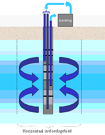
Figure: Diagram of recirculation source with multiple filtering. Extraction at middle filter, the above-ground purified water is re-infiltrated to lower and upper filter. The highlighted water flows are thus created. The horizontal catchment area is strongly determined by the scale of stratification in the soil (relationship Kh/Kh).
This cleaning approach does not lower the ground-water table, which is an advantage. One possible disadvantage is the difficulty in controlling diffusion which could be caused by such systems.
Technique 2: Deep well
A deep well consists of a vertical bore hole with a diameter of 100 to 600 mm, within which an extraction pipe is placed that has a perforated section (filter) and sand trap, surrounded by filter gravel. An underwater pump is placed in the pumping well, which brings the water to a height at which it can be drained using a discharge pipe. Besides the pumping well, a level indicator is often also placed in the bore hole in order to measure the level of ground-water in the deep well. If the ground-water reaches a particular height, it can also be extracted using a vacuum pump at ground level. The diameter of the bore hold (100 to 600 mm) and the filter are determined by the diameter of the pump, which is in-turn dependent of the desired extraction volume. The depth of the deep well depends on the required filter surface and the ground-water level, and takes ground-water sinking into account. With a longer and deeper filter, the drainage volume will increase. The rising pipe and the filter are mainly made of HDPE or PVC. The filtering material is determined by the soil texture. If the water-separating clay or peat layers in the soil are cut, the filtering material level to these layers is sealed with clay pellets/bentonite .
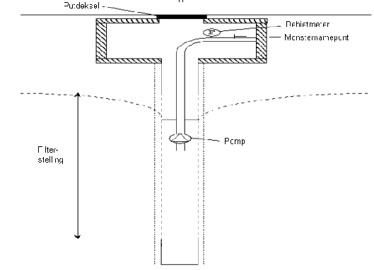
Figure: Deep well diagram
Technique 3: Vacuum filters
Vacuum filters are used for the extraction of (ground) water. Vacuum filters are vertical synthetic tubes with a perforated section, which is normally drilled or extruded into the ground (extrusion is only permitted in non-polluted zone), though in principle, pulsing, auger boring and compression are also possible). The vacuum filters are attached to a (ring) pipe, which is subject to sub-normal pressure. This helps to extract the ground-water and lower the ground-water level. The diameter of filters is normally 50 mm (2 inches), though larger ones can also be employed.
In general, filters are made from PVC. In long-term ground-water extractions, due to the chemical resistance, HDPE or another material may also be used. The vacuum tube (row filters) is attached to a vacuum pump. If the ground-water table sinks below the top of the perforated section of a filter, air is sucked in and the drainage stops. This can be prevented by:
- Making sure that the perforated section is placed deep enough.
- Fitting extraction tubes ( or hangers) to the filters
An extraction tube is an un-perforated pipe or tube, which is attached inside the filter, whereby the under-side is set slightly (circa 0.10 m) above the under-side of the filter. The extraction tube is then attached to the ring-pipe. The water streams through the filter and is pumped up via the extraction tube (also called gravity drainage).
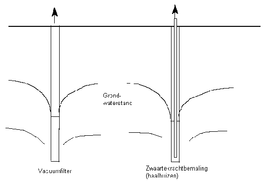
Figure: Vacuum filters Diagram
Technique 4: Drain
A drain is a perforated pipe, with or without a sheath, which is laid horizontally in the ground.
The drain can be laid:
- Mechanically, with a drainage machine, up to maximum 5 m under ground level (deep drainage can go to ca. 6 to 7 m under ground level);
- Manually, by digging a trench. For this, the ground-water level must be temporarily lowered.
- Horizontally placed bores from ground level. The bore hole is supported by a bentonite or a biologically degradable support fluid. This technique is in development.
- Horizontal compactors from a coffer-dam. For this, the ground-water level in the coffer-dam must be temporarily lowered.
The drain can be linked to a pump well by using an under-water pump (free decay) or a concealed pipe on the vacuum pump.
The drain is generally made from ribbed PVC and diameters can vary from 50 to 200 mm. The drains can also be equipped with polyethylene (HDPE) or polypropylene (PP), should the ground-water be very polluted. Drains can be coated with synthetic fibres. PP is most commonly used as coating material. There are various types of PP 700/450/350. Type PP 700 means a polypropylene sheath, with a characteristic pore size of O90 of 700 (90% of pores are smaller than 700 µ m). The material for the drain and the sheath is selected on the basis of:
- soil texture
- chemical resistance;
- deposit-forming (e.g. iron)
- sustainability;
- quality
Due to the strength of the material, a HDPE drain without sheath is implemented for boring and compacting techniques. Ideally, drains need to be placed in a capsule of drainage sand. It is not currently possible to implement a sand capsule in boring and compacting techniques.
The drains must be fitted with flushing devices and unattached drain-ends are fitted with a surface container at ground level.
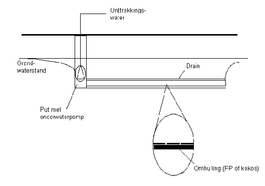
Figure: Drain diagram
Implementation area and implementation conditions
As a result of ground-water extraction, loam, clay or peat deposits may be created. If there is a risk of this happening, a deposit calculation needs to be carried out in order to qualify the deposit risk. In order to reduce the risk of deposits, (re) infiltration of water should be considered.
Technique 1: Recirculation well
The success of recirculation wells is mainly determined by the following factors:
‑ Geochemical conversion (inc. Iron precipitation, calcium-carbonates, gas-forming)
‑ Geochemical conversion (inc. Iron precipitation, calcium-carbonates, gas-forming)
Iron may precipitate if oxygen-free iron-rich water comes into contact with oxygen.
‑ Hydrological problems (inc. heterogeneity of soil);
The permeability of the soil in a vertical and horizontal direction is mostly difficult to estimate due to the shortage in information relating to geo-hydrologic soil structure);
‑ Physical problems (inc. Colloidal blockages);
Due to the in-flow of fine particles, the infiltration means (and/or outlet) can become blocked;
‑ Biology (inc. increase of bio-mass);
Due to the flow of nutrients or oxygen, biological activity may be increased whereby the infiltration means can be blocked by microbial growth.
‑ Dimensioning problems (inc. placement of too few re-infiltration wells). The infiltration capacity of an infiltration well is mostly 50 to 80% less than that of an extraction well.
Technique 2: deep well
The advantages of deep wells as a means of extraction are:
- also usable with high soil permeability;
- suitable for large extraction volumes;
- adjustable to the type of the ground-water pollution;
- not restricted by present underground obstacles;
- suitable for long-term drainage or cleansing.
Technique 3: vacuum filters
Vertical vacuum filters for ground-water extraction can be used for:
- Low soil permeability, low volume;
- Irregular form of ground-water pollutants or excavation;
- In combination with soil air extraction (‘dual phase’, multi-phase or ‘bio-slurping’)
- Obstacles provide no hindrance;
- Short-term drainage/clean up (less than 1 year) relating to low maintenance possibilities.
For the implementation of vacuum filters in long-term extractions (ground-water/soil air) it is recommended that filters be applied via holes made with a bailer. This allows the filters to be placed with a gravel surround and clay seals. For large volumes in a small drainage area, the filters’ limited surface area can be a limitation.
The theoretic sub-normal pressure is maximum ca.10 water column. In practice, the water cannot be induced further than 7 to 8 m (suction pump, centrifugal pump): 5 m). If this is a problem, one can try to place the pump lower down, by multi-layer drainage, for example.
If the discharge pipe (ring pipe) is fitted underground (long-term extraction), it would be sensible to place each filter at ground level with a surface container, so that the filters are independently accessible and can be rinsed.
As a result of ground-water extraction, loam, clay or peat deposits may be formed. If there is a risk of this happening, a deposit calculation needs to be carried out in order to qualify the deposit risk. In order to reduce the risk of deposits, (re) infiltration of water should be considered.
In the event of high iron content, it would be sensible to realise vacuum drainage with lowering containers, in order to prevent air suction and to combat precipitation from iron oxides as effectively as possible.
Technique 4: drain
A drain can be used for the extraction of ground-water, in the following cases:
- poor soil permeability or low volumes
- long-term, shallow ground-water pollutant or excavation.
- in combination with soil remediation: drain in soil excavation;
- no underground obstacles.
Costs
An indication of the costs for the various techniques is given in the table below. The total costs are determined by the present polluting substances, filter depth, volumes, system configuration, system management, terrain accessibility, disposal possibilities and distances to compactors.
Table: Ground-water extraction costs (excluding piping work)
|
Specifications material/implementation format |
Costs |
|---|---|
|
Deep well |
€ 125-200 per m deep well placing cost and € 37-125 per week per pomp exploitation |
|
Drain
|
€ 15-40 per m placement and € 50-150 per week per pomp exploitation costs € 75-200 per m placement and € 75-150 per week per pomp exploitation costs |
|
Vacuum filters |
€ 50-75 per m placement and € 75-150 per week per pomp exploitation costs |
|
Re-circulation well |
2500 to 25000 euro per filter, inclusive of pump system. |
Costs for a are greatly determined by the depth. Cost price per filter normally falls within a range of 2500 to 25000 euro, inclusive of pump system.
Environmental burden and measures to be implemented
Initially, the extracted ground-water can be regarded as harmful to the environment. The discharged waste water stream must be purified. There are number of techniques available, see table below for the Best Available Techniques for ground water purification:
|
Pollutant |
Technique |
|---|---|
|
VOCl |
|
|
BTEX |
|
|
Mineral oil |
|
|
PAK |
|
|
Naphthalene |
|
|
Heavy metals |
|
|
MTBE |
|
|
BOD/COD/suspended solids |
|
During the extraction of ground-water, there is a risk that pollutants may be released into the air (an air outlet is only present in vacuum pumps). Undesirable emissions into the air may occur in pump containers, buffer tanks, biological purification (bio-rotor) or during air stripping of extracted ground-water.
A waste stream, of drilled or excavated polluted ground, could possibly be released when extraction and infiltration filters are placed. In addition, a waste stream of activated carbon or polluted silt, may be released during the purification of ground-water. In most cases, this waste stream is disposed of or incinerated. If a regeneratable activated carbon filter is used, the carbon can be re-used.
The extraction of ground-water provides relatively few problems to the environment. Extraction and infiltration filters are mostly placed underground, so that they present no problems. Only compressors and pumps may lead to noise-related problems. Buildings can remain intact and roads do not have to be dug up. In placing this installation, and possibly the clean up installation, short-term problems may arise from lorry transport.
[1] in combinatie met zandfiltratie