Synonyms, abbreviations and/or process names
- Regenerative afterburning
- Thermoreactor
Removed components
- VOC
- Odour
- Halogenated organic compounds
- CO
- (Fine organic particles)
Diagram
Process description
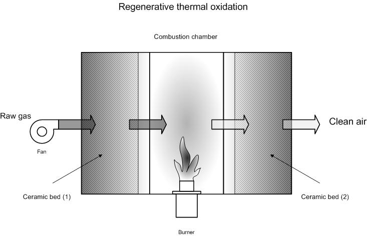
Regenerative afterburning differs from classic afterburning without heat recuperation because 2 or 3 ceramic beds are used. These ceramic beds are used to store heat from cleaned flue gases, and to later use it for polluted gases.
In a system with two beds, the polluted gas is passed through the first ceramic bed, where it absorbs heat stored in that bed. When leaving the ceramic bed, the gas begins to approach combustion temperature or combustion has already started autothermally.
In the combustion area, the gas is further heated via burners so that thermal oxidation takes place or combustion continues if autothermicity has started.
The hot gases leaving the combustion area are then passed through the second ceramic bed, where they give off the majority of their heat, and thus cause the temperature of the 2nd bed to rise. The cooled gases are then removed. In time, when the 1st bed has cooled sufficiently and the 2nd bed has heated-up sufficiently, the direction of the gas flow is reversed. The 2nd bed then helps to heat the polluted gas stream, and the 1st bed helps to cool cleaned gases. When the gas flow is reversed, pollutant emissions will peak because the gases present in the bed (due to pre-heating) have yet to be burnt and will be sent to the chimney once reversal has taken place.
In a system with three beds, the 1st bed is used to pre-heat the polluted gas stream, the second bed to cool cleaned gases, and the 3rd bed is purged with (part of) the combustion air from the second bed in order to remove present VOC’s. Upon reversal, the purged bed is heated with combustion gases, the heated bed is used to pre-heat gases and the pre-heating bed is purged.
A 3-bed system is required to realise complete destruction of pollutants or, in a two-bed system, an extra buffer chamber can be added to buffer gases upon reversal and to then return them to the active reactor.
With regenerative afterburning, an energy recuperation of 85 – 98% can be realised. Yields of at least 95% are being guaranteed by some suppliers. The ceramic beds are suited to temperatures up to 1 100 °C, without any problems.
The yield for heat recuperation can be as high as 98%. This makes autothermic combustion possible from 1 -2 g/m³ of solvent [5,9]. For heat recuperation between 90 and 95 %, an autothermic concentration limit of 1 -3 g/m³ has been indicated [12].
For high solvent concentrations, only a part of the hot gases is passed over the ceramic bed in order to prevent the bed from over-heating. The hot gases that are not passed over the bed can be used for heat recuperation – heat which can be used for process purposes.
Variants
Besides systems with 2 or three fixed ceramic beds (see process description), other implementation methods are also possible. A couple of examples are ceramic rotors and moving beds.
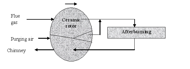
Ceramic rotor
In a ceramic rotor, a cylindrical bed revolves around its axle (see figure below). As the rotor revolves, it is alternately heated and cooled. In order to avoid, emitting part of the flue gases to the chimney along with cleaned gases, as in two-bed systems (see description), one can use a compartment where purging takes place with fresh air. This air goes to the afterburner along with the flue gases.
Energy recuperation with moving bed
In ‘moving bed’ recuperation, the gas is passed upwards through a bed of ceramic grains. Flue gases are heated in the lower section. There is an open space in the centre of the bed, with a burner to combust the gas. The fumes continue to rise in the bed and heat the bed above the burner. By taking grains from the bottom of the bed and replacing them at the top, the bed continuously sinks whereby one realises continuous heating and cooling.
Efficiency
The efficiency for VOC-destruction is 95 - 99%. The yield is lower than classic afterburning without energy recuperation (see technique sheet 30) because regenerative afterburning is implemented at lower VOC concentrations. At lower concentrations, there is less destruction efficiency. The yield can also drop if only two beds are available.
The attainable VOC end concentration is like that of classic afterburning < 1 – 20 mg/Nm³.
CO and dioxins are removed with yields similar (a little lower) to afterburning without energy recuperation, if the correct boundary conditions are implemented (see technique sheet 30).
Boundary conditions
Regenerative afterburning is suited to [4]:
- Large flow rate: > 8 500 Nm³/h
- Particularly suited to low VOC concentrations < 1 000 ppm
- Autothermicity is realised from 1 – 2 g solvent/Nm³.
One must be wary of condensable substances (e.g. fats) and dust being present in to-be-cleaned gases. These may block the ceramic bed, which will increase the pressure drop across the bed.
Under normal circumstances, dust concentrations must be less than 3 mg/m³ [5].
If 3 or 4 beds are being implemented, one bed can be periodically "burnt-out" by increasing the temperature across the entire bed. Afterburning can continue to take place simultaneously. During burn-out, the organic substance and sticky build-up are burnt off the ceramic grains. This allows one to reduce the bed’s pressure drop. In this case, the presence of dust is a little less critical. Though it does sharply increase investment costs.
A continuous production schedule is ideal for regenerative afterburning. If the process is halted, the beds will cool down and natural gas will be needed to re-heat the beds. As a guide, a work schedule with 2 shifts per day, 5 days per week has been outlined.
In the interest of safety, the hydrocarbon concentration in the flue gases must be kept below 25% of the lowest explosion limit (LEL).
Auxiliary materials
Normally no auxiliary materials required. The ceramic material has a very long life-span.
Environmental aspects
End concentrations are similar to classic afterburning without energy recuperation.
Specific to thermal regeneration [5]:
- NOx < 50 mg/Nm³
- CO: < 50 mg/Nm³
- VOC: < 20 mgC/Nm³
Specific to thermal regeneration [8]:
- NOx: < 20 mg/Nm³
- CO: < 20 mg/Nm³
- VOC: 200 - < 20 mg/Nm³
Also specific to thermal regeneration [12]:
- NOx; 20 – 50 mg/Nm³
- CO: < 100 mg/Nm³
- VOC: < 20 mg/Nm³
Energy use
Energy use is a lot lower than classic thermal afterburning without energy recuperation and is determined by the solvent load in gases. Autothermic combustion is possible from 1 -2 g/m³ of solvent [5].
If the installation is not used continuously, energy will also be needed to heat the ceramic beds up to operating temperature on a daily or weekly basis. This leads to extra energy costs.
The ventilator accounts for a vast amount of energy use. Ventilator capacities are high due to the high pressure drop of the ceramic bed (also refer to cost aspects; examples: ceramics industry)
Cost aspects
Investment
- 20 000 – 30 000 EUR for 1 000 Nm³/h [2, 9]
- 24 000 -89 000 USD for 1 000 Nm³/h [2,4]
- 22 000 -29 200 EUR for 1 000 Nm³/h [2]
- 30 000 -75 000 EUR for 1000 m³/h for flow rates of 5 000 m³/h [6]
- 12 500 – 35 000 EUR for 1000 m³/h for flow rates of 20 000 m³/h [6]
- 68 000 EUR for 1000 m³/h for flow rates of 5 000 m³/h [12]
- 32 000 EUR for 1000 m³/h for flow rates of 20 000 m³/h [12]
Operating costs
- Personnel costs: ca. 2 days per year [1]
- Operating costs:
- Examples:
- Examples of regenerative adsorption followed by afterburning can be found here
Glue spraying booth case study [6]
- 10 000 m³/h
- 1 270 mg C/Nm³
- 16 hours per day operation
- Investment costs: 274 000 EUR excl. VAT
Glue spraying booth case study [6]
- 15 000 m³/h
- 2.2 -3.0 g/Nm³ solvent
- 16 hours per day operation
- Investment costs: 302 000 EUR excl. VAT
- Electricity use: 40 kW
- Fuel use: 0 – 32 kW
Glue spraying booth case study [6]
- 25 000 m³/h
- 1.5 g/Nm³ solvent
- 16 hours per day operation
- Investment costs: 342 000 EUR excl. VAT
- Electricity use: 46 kW
- Fuel use: 114 kW
Investment in small afterburner [6]
- 1 500 – 4 500 Nm³/h
- 0 -2.8 g/Nm³ solvent
- Investment costs: 204 000 EUR excl. VAT
- Fuel use: 0 -122 kW
Investment in polyester plant [6]
- 5 000 Nm³/h
- Yield 99%
- Rotating ceramic bed
- Investment costs: 250 000 EUR excl. VAT
Investment in coating activities [6]
- 15 000 Nm³/h
- Yield 99%
- Rotating ceramic bed
- Investment costs: 300 000 EUR excl. VAT
Investment in laminate production [6]
- 23 000 Nm³/h
- Yield 99%
- Rotating ceramic bed
- Investment costs: 350 000 EUR excl. VAT
Investment ceramic industry [6]
- 19 000 Nm³/h
- Yield 95 -97 %
- Two-chamber system
- Investment costs: 285 000 EUR excl. VAT
Investment printing sector [6]
- 15 000 Nm³/h
- Yield 95 -97 %
- Two-chamber system
- Investment costs: 300 000 EUR excl. VAT
Investment impregnation line [6]
- 24 000 Nm³/h
- Yield 99%
- Rotating ceramic bed
- Investment costs: 390 000 EUR excl. VAT
Investment wood-drying [6]
- 33 000 Nm³/h
- Yield 99%
- Three-chamber system
- Investment costs: 590 000 EUR excl. VAT
Treatment of gases in the ceramics industry [6]:
- The investment costs are shown in the table below.
- Investment costs fulfils best the following exponential comparison:
|
Installation |
Investment cost: (EUR) |
Flow rate Nm³/h |
Investment cost per 1000 Nm³/h |
|
1 |
655 259 |
64 235 |
10 201 |
|
2 |
693 354 |
73 300 |
9 459 |
|
3 |
565 356 |
73 300 |
7 713 |
|
4 |
418 986 |
25 920 |
16 165 |
|
5 |
499 714 |
37 530 |
13 315 |
|
6 |
499 714 |
37 970 |
13 161 |
|
7 |
529 169 |
39 688 |
13 333 |
|
8 |
565 356 |
48 445 |
11 670 |
- Electricity cost: 1.5 – 2.25 kW/1 000Nm³/h. Low value for temperature after 170 °C afterburner and high value after 260 °C.
- Compressed air approx. 16 m³/h
- Maintenance approx. 5% of investment
Investment for coating of concrete tiles [7]
- Cost aspects for treating flue gases from coating and drying processes
- Annual production of 90 000 ton coated tiles
- Investment costs: ca. 750 000 EUR
Treatment of gases in the ceramics industry [10]:
- Flue gas flow rate: 30 000 Nm³/h
- VOC concentration: 250 mgC/Nm³
- Investment costs: ca. 550 000 EUR
- Annual operating cost: 100 000 EUR incl fuel, electricity, repairs and maintenance
Advantages and disadvantages
Advantages
- No erosion problems from the heat exchanger (as with recuperative afterburning) or poisoning from the catalyst via metals or halogens (as with catalytic afterburning).
- The gas stream is homogenised as it passes through the bed.
- Very thorough energy recuperation: 85 – 95 %
- Relatively low operating costs
- Autothermic operation with low VOC concentrations (from 1- 2 g/m³ solvent [5])
- Very low residue concentrations for VOC, NOx and CO
Disadvantages
- High investment costs
- Ceramic beds may be blocked by dust and condensed particles.
- In discontinuous operation, the bed must be re-heated every time, using extra fuel.
- Large size and weight
- A lot of maintenance and moving parts
Applications
Regenerative afterburning is primarily used for:
- High flow rates;
- Low VOC concentrations;
- Continuous operation of plant.
- Odour removal from gases with low organic content
Sectors in which regenerative afterburning is used:
- Printing
- Production of laminates
- Paint workshops
- Chemicals industry
- Odour reduction in wood drying
- Ceramics industry
- Manure processing
References
- Factsheets on Air-emission reduction techniques, www.infomil.nl, Infomil
- BREF: "Common waste water and waste gas treatment /management systems in the chemical sector" EIPPC, February 2002
- EPA Air Pollution Technical factsheet: Thermal incinerator
- EPA Air Pollution Technical factsheet: Regenerative incinerator
- VDI 2587 part 1: Emission control: heatset web offset presses, November 2001
- Supplier information
- A. Jacobs, J. Van Dessel and R. Dijkmans., Best Available Techniques for Concrete plants and the Concrete-production industry, February 2001
- L. Goovaerts, Y. Vreys, P. Meulepas, P Vercaemst and R. Dijkmans., Best Available Techniques for foundries, March 2001
- A. Jacobs, B. Gielen, I. Van Tomme, Ch. De Roock and R. Dijkmans., Best Available Techniques for the wood processing industry, October 2003
- D. Huybrechts, P. Vercaemst and R. Dijkmans., Best Available Techniques for the clay-processing industry, 1999
- T Feyaerts, D. Huybrechts and R. Dijkmans., Best Available techniques for manure processing, edition 2, October 2002
- L. Goovaerts, M. De Bonte, P. Vercaemst and R. Dijkmans., Best Available Techniques for the metal processing industry, December 2003
- A. Derden, J. Schrijvers, M. Suijkerbuijk, A. Van de Meulebroecke1, P. Vercaemst and R. Dijkmans., Best Available Techniques for the slaughterhouse sector, June 2003