Synonyms, abbreviations and/or process names
- Biobed
- Biobed filter
- Biological filter
- Compost filter
Removed components
- VOC
- Odour
- (NH3)
- (H2S)
Diagram
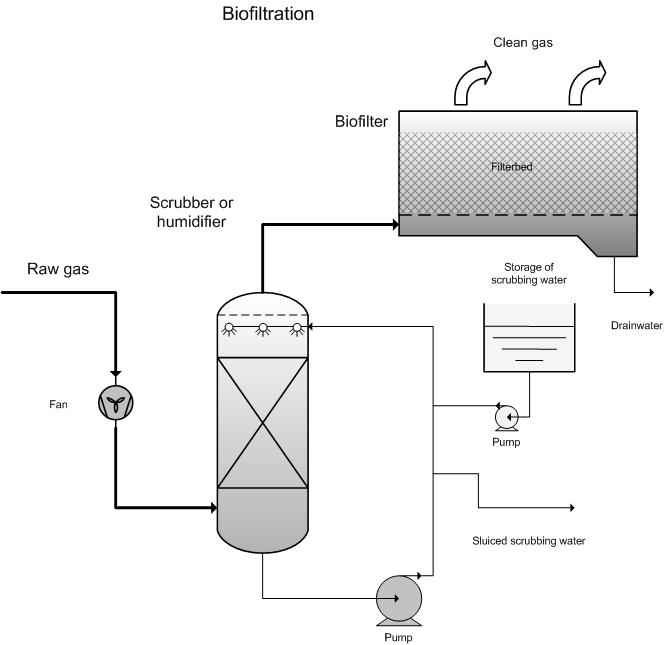
Process description
In a biofilter the to-be-cleaned gas stream is passed upwards through a filter bed, which has been constructed of biological material, for example, compost, tree bark or peat. The filter material carries a thin film of water which is home to micro-organisms. The pollutants in the gas stream are retained in the filter material via adsorption and absorption, and are then decomposed by the present micro-organisms. The filter material serves as a supplier of necessary nutrients. The degradation products for conversion are carbon dioxide, sulphate, nitrate etc.
The dry matter content in the filter typically varies between 40 to 60%. To prevent the bed from drying-out, the gas stream must be fairly well saturated with water. This is why to-be-treated air is normally moistened in advance. This can be done with a pre-implemented scrubber. The gas must have a relative humidity of 95% [5]. In practice, it is always better to implement a humidifier in advance, in order to prevent the filter from drying out.
The filter material naturally contains enough different types of micro-organisms to deal with easily-degradable substances. In case of substances that are more difficult to degrade, the filter can be injected with special cultures in order to realise faster filter start-up, though close follow-up is essential to safeguard correct working parameters. The addition of minerals and nutrients may be desired if there is insufficient nutrient-release in the filter material.
Mixes of easy to degrade and difficult to degrade substances are difficult to break down in a biofilter because, first and foremost, the easily degradable substances are broken down, while the more complex substances are left behind.
During the design of the biofilter, the required bed volume is calculated via the breakdown rate of components in the flue gas. If the bed height is know (normally 1 -1.5m), then the required biofilter surface can be calculated. The biofilter can be customised on-site or can be purchased in pre-set modules. Depending on the load and the flow rate, multiple modules can be placed next to one another. The typical surface load for a biofilter amounts to 50 - 300 m³/m²h, but can be as low as 5 and as high as 500 m³/m²h.
In biofiltration it is important for the filter material to have a pH between 7 and 8 for the break-down of organic components. The break-down speed reduces quickly at pHs less than 6.5.
The residence time for the gas in the filter must be at least 30 – 45 seconds in order to effectively realise odour and solvent removal. According to BAT [13] the required residence time lies between 20 seconds and 1 minute.
When the packing is being introduced, one must ensure that the filter material is well distributed and that there are no solid of loose zones. These could lead to open streams, causing sub-standard air treatment and reducing the effective filter surface. The filter dries out quicker at the places where there is favourable air passage, which again reinforces this effect. If the filter material is systematically loaded with trucks at one side, this can easily create difficult-to-permeate zones and zones that are easy to permeate, which will quickly cause the biofilter to perform poorly.
It is necessary to closely follow-up filter operation so that one can react quickly when there is a reduction in the filter material’s efficiency.
Variants
- Multiple layers of filter material
Sometimes multiple layers are used to form various bacteria cultures. The easily degradable components are removed in the first layer. The second layer will primarily deal with components in the flue gas that are more difficult to degrade. This is where specialised (mostly slow growing) bacteria are found.
- Open or closed
The biofilter can be open or closed at the top. In an open biofilter, the biofilter will be subject to rain, sun, moisture… This may cause plant growth; after excessive rain, the biofilter could be too wet; after sunny periods the biofilter may be too dry. A closed biofilter is better protected against external weather conditions and can be better managed and followed-up.
- Air inflow above or below the filter bed
This is the most widely implemented type of biofilter. For inflow below the bed, biological degradation and irrigation take place in different areas. Moisture build-up may occur in the filter due to air channelling, which may cause anaerobic zones to be created at these places. By placing a piping system close to the air inlet at the bottom of the bed, it is possible to rinse polluted degradation products from the bed without causing a lot of damage to the filter material. Because the concentration of polluted substances is normally low in the top part of the bed, the filter can normally be easily inspected without troublesome safety issues.
For an inlet above the bed, irrigation and biological degradation primarily take place above the bed. The bed will have a more consistent moisture level because unsaturated air and humidification enter the bed at the same place. This means there is less risk of local moisture build-up. Bi-products such as acids can also percolate through the bed, which may damage the filter material. It is also impossible to wash particles from the bed. In the interest of safety, the installation must be switched off for maintenance and must be well-ventilated in order to remove organic substances from the space above the biofilter.
- Biofilter with bacteria or moulds
Classic biofilters normally make use of bacteria. A more recent development is the implementation of moulds. These are more resistant to dehydration, acidification and blocking of the filter. In the case of biofilters with moulds, there are no known examples of full-scale installations. Further research is still required to make this technique effective on a larger scale.
- Type of filter material
Depending on availability and the requirements of the biofilter, it is possible to amend the composition of the biofilter material. Here are some examples of filter materials: compost, tree bark, heath, peat, burr, coconut material, expanded materials… Each of these filling materials has its specific properties in terms of specific surface area, stability and life-span, resistance against acidification and air resistance. It is also possible to implement a combination of materials. In order to avoid acidification, one could add buffering materials, such as lime and dolomite, to the filling material.
A chemical scrubber is sometimes used to remove acidifying components before the biofilter is implemented. These acidifying components include ammonia, amines, sulphur components, chlorides… The scrubber acts as a pre-treatment and the biofilter ensures further degradation of the pollutants.
Efficiency
Typical removal efficiencies lie between 60 and 100 %, depending on the composition of the flue gas and the physical condition of the filter material [1].
|
Component |
Yield (%) |
End concentration (mg/Nm³) |
|
Hydrocarbons |
75 – 95 |
> 5 |
|
Odour |
75 – 95 |
> 5 000 ou/m³ |
|
Styrene |
80 – 90 |
> 10 |
|
Toluene |
80 – 95 |
> 5 |
The odour removal yield (concentration expressed in odour units per m³, ou/m³) in flue gases derived from processing animal waste at a stable, amount to an average of 95.6 – 99.76 [4] for an effective biofilter.
An end concentration less than 500 ouE/m³ [6] is required in Germany. The residual odour from the biofilter itself amounts to 200 – 500 ouE/m³ [2], which makes it difficult to realise the target.
In cas of odour problems, attention must also be paid to the pipes connected to the biofilter. These may become a secondary odour source if substances build up and create an anaerobic layer.
The yield for removing hydrocarbons is 80 – 99 %. For a flow rate of 20 000 m³/h and an in-coming concentration between 643 and 1 300 mgC/Nm³, the out-going concentration is 40 – 100 mgC/Nm³ [12].
Boundary conditions
- Flow rate: 100 – 100 000 m³/h
- Temperature: 15 – 35 °C ; for T < 15 will reduce efficiency; if T > 35 °C then coling is needed, except for thermophilic operation (45 - 60 °C), though thermophilic operation is less stable than normal operating temperature [6];
- Relative humidity: > 95 % (place spraying towers if necessary)
- Pressure: atmospheric
- Hydrocarbons: 200 – 2 000 mg/m³ [2]: max. 800 mg C/Nm³ [6]
- Odour: 20 000 – 200 000 ou/m³ [2]
- Toluene: 20 – 100 mg/m³ [2]
- Styrene: 50 -500 mg/m³ [2]
- The to-be-treated air must be dust-free to prevent the bed from blocking. [2]
- The emission must be fairly consistent, in terms of flow rate and composition, in order to get an effective response from the biology. Concentrations and loads that fluctuate greatly can lead to a reduction in yield. In case of fluctuating loads, an activated carbon filter or another buffer can be used to spread concentrations.
- There must be a relatively consistent emission supply. Biological techniques are not suited, or are less suited, to work schedules less than 8 hours per day, 5 days per week.
- After being stationary for 3 weeks, it can take a few weeks for the biofilter to realise the yield it had prior to being stationary. It is important to continuously aerate the biofilter in order to avoid anaerobic conditions.
- Sulphur, chlorine and nitrogen-laden organic components may, in concentrations greater than 10 - 20 mg/m³, acidify the biofilter material by forming sulphuric acid, hydrochloric acid and nitric acid respectively, and lead to a reduction in removal efficiency. Acidification will lead to the filter material needing replacement sooner than otherwise. Acidification can be combated by adding buffering substances such as limestone, which will help to extend the placement time of the filter bed.
- A high concentration of NH3 in flue gases can lead to acidification and salinification of the biofilter via the forming of nitrate and ammonium nitrate. The maximum concentration of NH3, for operation without acidification, is 10 mg N-NH3/Nm³. Concentrations up to 50 mg/Nm³ can be realised, but the filter material will need to be replaced more often.
Auxiliary materials
Filter material
The filter material must be replaced periodically (every 0.5 – 5 years). The timeframe within which it must be replaced is determined by the type of filling material and the composition of flue gases. The material will need to be replaced if pH is too low, if the pressure drop is too high after compacting the biomass or if the carrying material has salinified, whereby filter efficiency is insufficient.
Spray water to vaporise the filter material and incoming air.
Environmental aspects
A small amount of percolate water is released by the biofilter. This water is laden with degradation products (nitrate, sulphate…) and a few organic substances and must be discharged into the sewage system or surface water, possibly after treating the percolate.
Carrying material is periodically released (every 0.5 – 5 years) and must be disposed of and processed via composting, land-filling or incineration.
Energy use
The biofilter itself uses little energy (< 1 kW/1 000 m³/h). The energy use is primarily determined by the ventilator, which has to compensate for the pressure drop. This pressure drop amounts to 500 Pa for a compost filter and 1 500 Pa for a soil filter [1].
A guideline value of 0.05 – 0.1 kWh/1000 m³ has been stated by BAT [11], whereby calculation takes place based on a pressure drop of 100 – 250 Pa.
Because a biofilter must be continuously aerated, also when there is no production, one should count on 8760 hours per year. During periods when there is no production, a reduced flow rate can be processed to limit pressure drop, flow rate and energy costs.
Cost aspects
Investment
- 5 000 – 20 000 EUR per 1 000 Nm³/h [2]
- 290 – 13 100 EUR per m³ filter volume [2]
- 10 000 – 15 000 EUR per 1 000 m³/h [6]
- 4 500 – 114 000 EUR per 1000 m³/h [12]
An "Investment vs. Flow rate" cost curve has been obtained on the basis of case studies [9]:
I = 45,424 x FR0,808
I: Investment costs (€)
FR: Flow rate (m³/h)
In order to account for the extra costs for peripherals etc., a factor of 1.85 must be used for this investment. This factor considers instruments, transport, foundations and construction, placement of electricity, piping, insulation of ventilation pipes, paints, engineering, contracting costs, start-up, operation checks and unexpected costs.
Itotal = I x 1.85
Operating costs
- Personnel costs: 1 mans hour per filter per week + 2 man days per year [2]
- Auxiliary and residual materials: 5 litres of water per 1 000 Nm³ [2] + Approximately 200 EUR/m³ filter material (replacement every 0.5 – 5 years) [2]
- Total operating costs: 725 – 1 450 EUR/1 000Nm³/h [2]
- Total operating cost: 0.36 EUR/1 000 m³ [6]
- Total operating costs: 10 – 50 EUR per 1 000 Nm³ flue gas for flow rates of 5 000 Nm³/h [10,12]
Factors that influence cost aspects:
- Gas volume
- Concentration of pollutants
- Gas composition
- Flue gas temperature
- Emission characteristics
- Required efficiency
- Type of filter material
- Type of nutrients added
Specific projects:
Flue gas from water purification, with odour and VOC [3]
- Flow rate: 60 000 – 75 000 m³/h
- Concentration: Chlorine-laden hydrocarbons = 25 – 50 mg/m³, aliphatic hydrocarbons = 50 – 100 mg/m³, aromatic hydrocarbons = 200 – 250 mg/m³, other hydrocarbons = 50 – 100 mg/m³.
- Operation: 80 % removal
- Investment costs: 4 000 000 USD (1990); according to this constructor, the same installation can be constructed for 50 % of the price
- Operating cost: 1.44 USD per 1 000 m³
Flue gas from an odour and flavourings factory [3]
- Flow rate: 22 000 m³/h
- Concentration: Odour components: Concentration of 2 000 ouE/m³
- Operation: 95 – 99 % odour removal
- Investment costs: 375 000 USD incl. placement (1995)
- Operating costs: 0.06 USD per 1 000 m³
Flue gas from drying printing ink [3]
- Flow rate: 76 000 m³/h
- Concentration: 100 mg/m³
- Operation: 85 – 95 % for non-methane components
- Investment costs: 1 000 000 USD incl. placement (1997)
- Operating costs: 0.065 USD per 1 000 m³
Odour emission from a foundry [6]
- In-going:
- 80 000 m³/h
- 50 – 140 mg C/Nm³
- 500 – 1 000 ou/m³
- Efficiency:
- TOC: 35 – 70 %
- Odour: 77 – 93 %
Investment costs:
- Biofilter = 385 000 EUR
- Filter material (750 m³) = 50 000 EUR
- Venturi scrubber = 280 000 EUR
- FID measurement = 50 000 EUR
- Waste water purification = 200 000 EUR
- Other = 100 000 EUR
- Total = 1 065 000 EUR
Operating costs:
- Electricity = 75 000 EUR/year
- Water usage = 10 000 EUR/year
- Filter material (8-year standing time) = 10 000 EUR/year
- Maintenance = 75 000 EUR/year
- Total = 170 000 EUR/year
Electricity costs can be primarily attributed to the venturi scrubber, which has a high pressure drop.
Odour emission from a waste processor [8]
- Flow rate: 35 000 m³/h
- Suction throughout processing halls and storage tanks
- Two-stage biofilter with 140 m² surface area
- Spray vaporiser equipped with humidification and dust-removal
- Operation: 95 % pre-determined with minimum 3 000 ou/m³ at output
- Investment costs: 243 500 EUR excl. VAT
- Investment
- Including placement of parts + start-up
- Excluding piping between various components, construction works, connection to the utilities at the company
Treatment of ventilation air from a pig stall [8]
- Flow rate: 43 000 m³/h
- Investment costs: 34 700 EUR excl. VAT
- Annual costs: 0.02 EUR per 1000 m³
Applications
Biofiltration is primarily used for large flow rates, low solvent concentrations and when there are odour problems.
Typical areas for implementation are:
- Water purification plants
- Composting installations
- Flavourings industry
- Foundries
- Chemicals industry
- Plastic production
- Foodstuffs industry
- Meat and fish-processing industry
Advantages and disadvantages
Advantages
- Low investment and operation costs
- Simple construction
- Effective removal of biologically degradable components (also water soluble components like xylenes, styrene…)
- Low pressure drop
- Little waste water (percolate water)
- Little waste material (only replaced filter material)
Disadvantages
- Large surface area needed (this can be resolved by placing the container biofilters on top of each other so that the surface area is reduced; though this does increase the cost aspects)
- The filter material must be periodically replaced
- It is difficult to check the humidity and pH of the filter material
- Few configuration parameters to improve efficiency
- Risk of blockage due to dust
- Fluctuations in concentration have a big influence on efficiency
- The bed must be continuously aerated to avoid anaerobic conditions.
References
- Factsheets on Air-emission reduction techniques, www.infomil.nl, Infomil
- Common waste water and waste gas treatment and management systems in the chemical sector, BREF document, European IPPC Bureau, http://eippcb.jrc.es, 2002
- Process technique and engineering, Basis handbook for an engineer, Kluwer et al together with the Flemish Chamber of Engineering, 2002
- VDI 2590: Emission control: plants for the utilization and disposal of animal carcasses, either wholly or partially, and for the processing of animal products (rendering plants), December 1996
- VDI 3477: Biologische abgasreinigung biofilter, entwurf, August 2002
- VDI Seminar 434802 am 25 November 2003: Optimieren der biologischen abluftreinigung
- J.S. Devinny et Al.:"Biofiltration for air pollution control"Lewis publishers, 1999
- Supplier information
- EPA Air pollution Control Cost Manual. EPA-452-02-001. January 2002.
- A. Jacobs, B. Gielen, I. Van Tomme, Ch. De Roock and R. Dijkmans., Best Available Techniques for the wood processing industry, October 2003
- T Feyaerts, D. Huybrechts and R. Dijkmans., Best Available Techniques for manure processing, edition 2, October 2002
- L. Goovaerts, M. De Bonte, P. Vercaemst and R. Dijkmans., Best Available Techniques for the metal processing industry, December 2003
- A. Derden, J. Schrijvers, M. Suijkerbuijk, A. Van de Meulebroecke1, P. Vercaemst and R. Dijkmans., Best Available Techniques for the slaughterhouse sector, June 2003