Synonyms, abbreviations and/or process names
- Scrubber
- Absorption
Removed components
- Gaseous components
- Dust (certain types of application)
- Odour (certain types of application)
Diagram
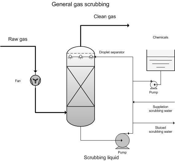
Process description
A scrubber is a waste gas treatment installation in which a gas stream is brought into intensive contact with a liquid, with the aim of allowing certain gaseous components to pass from the gas to the liquid. Scrubbers can be employed as an emission-limiting technique for many gaseous emissions. Scrubbing is also referred to as absorption.
During scrubbing there is a transfer of components from the gas phase to the liquid phase. The level of gaseous components that can pass to the liquid phase is determined by the ability of these components to dissolve in the liquid. Henry's Law is applicable to the solubility of gases in liquids, for low concentrations and components with a partial pressure < 1atm:
![]()
p = partial pressure (Pa)
x = mole fraction
H = Henry constant (Pa)
This allows one to calculate the maximum concentration of a particular component in the washing water, for the required end concentration. This also gives an indication about water usage under those circumstances.
The equilibrium concentration in the vapour phase, which corresponds to a certain concentration in the liquid phase, is determined by the temperature – the higher the temperature in the liquid phase, the higher the equilibrium concentration in the vapour phase. Thus a reduction in temperature has a favourable effect on the yield.
It is possible to increase the load by adding chemicals to the washing liquid, which help to convert absorbed components. Thus adding chemicals that react with the absorbed gases has a positive effect on the absorption yield.
Besides water (wet scrubbers), organic liquids are also used as absorption mediums. In many cases chemicals or micro-organisms are added to the scrubbing liquid to convert or neutralise gases that are dissolved in the liquid (conditioned scrubbers). As a result of this conversion, the concentration in the water is reduced, which in-turn allows more gas to dissolve (according to Henry’s Law).
The concentration of polluted substances in out-going gas streams can never become lower than that permitted by the equilibrium between the gas phase and the scrubbing liquid.
In practice, a scrubber consists of three parts: An absorption section, a droplet collector and a recirculation tank with pump.
Design data:
The liquid-gas ratio (L/G) in a scrubber is the relationship between the scrubbing liquid flow rate and the gas stream flow rate. For dimensioning purposes, and to evaluate the workings of a scrubber, it is important to know how much liquid is required per m³ to realise the required residual emission. The L/G ratio is not only determined by the required residual emission, but is also partly determined by the concentration of the to-be-removed substance(s) in the gas stream and the in and out-going liquid streams. The L/G ratio in a particular situation is thus determined by the selected scrubbing system, the properties of the to-be-cleaned gas, the scrubbing liquid and the to-be-removed component(s) and the requirements set for residual emissions.
Variants
Flow direction gas and liquid
Scrubbers can be distinguished in terms of the flow direction of the gas in relation to the liquid. A distinction is made between counter-flow, co-current and cross-flow scrubbers.
In counter-flow scrubbing the scrubbing liquid and the to-be-cleaned gas flow in opposite directions. The main advantage of counter-flow scrubbing is that the cleaner the gas becomes, the lower the pollutant concentration in the scrubbing liquid becomes - whereby the driving force is maintained throughout the column. This type of scrubber is, for example, particularly suited to irregular and peak emissions. The counter-flow set-up allows high concentration peaks to be better dealt with.
In co-current scrubbers, the gas and liquid stream move in the same direction. They are less effective than counter-flow scrubbers. However, the advantage they offer is that they are suited to high gas and liquid loads. Co-current scrubbers have a more compact construction and are normally considered when limited space is available and a lower yield is acceptable. Further, they are effective as an initial scrubbing stage for a counter-flow scrubber, for example, when the gas flow needs to be cooled or partly separated.
In cross-current scrubbers, the gas and the liquid move across one another. For vapour-like components, the liquid will normally flow in a downward direction and gases will flow horizontally. In dust scrubbing, the sprayers will be horizontal to the gas flow. This type of scrubber is more compact than a counter-current scrubber, if one works with a multi-stage set-up, and uses less electricity. A cross-current scrubber is suited to emissions with known maximum concentrations, thus allowing it to be dimensioned appropriately. In case of very high concentration peaks, for which the scrubber has not been dimensioned, the scrubbing liquid will be saturated before it reaches the bottom of the packing. This means that a part of the air will not be (fully) treated, with yield loss as a result.
Gas scrubber with or without built-in device:
Gas scrubbers can also be distinguished by the set-up of the wash section, e.g. with or without a built-in device. The built-in device could be a bulk or structured packing or a construction with plates or a rotating disk. The main layout can be further broken down as follows:
Gas scrubbers without built-in device:
- Spray towers: In spray towers the water is dispersed in fine droplets, normally via sprayers at the top of the scrubber, while the gas is fed from underneath – thus in counter-current. Set-up is also possible in co-current or cross-current formats. Can also be used as a dust scrubber.
- Jet scrubbers: In a jet scrubber, the gas and scrubbing liquid are brought into contact with one another in a co-current direction, in accordance with the workings of a water jet pump. In the wash section, the jet breaks down into droplets, which creates a large phase interface. In the next area, the gas and the liquid are separated.
- Venturi scrubber: A venturi scrubber consists of a converging section, a throat (the narrowest part of the venturi tube) and a diffuser. The gas flows through the venturi tube and reaches top speed in the throat section. Thereafter, the gas passes into the diffuser where the speed of the gas drops once again. The liquid is added to the gas flow either in the throat section or prior to it. Intensive mixing takes place between the gas and the liquid in the throat section of the venturi tube. Due to the high speed realised by the gas and liquid, the water is broken down into fine water droplets. Can also be used as a dust scrubber
Gas scrubbers with built-in device:
- Plate column: A plate column is a column which is divided into segments by perforated plates. The perforations have been designed in a way that forces the to-be-cleaned gas to bubble through a sealed fluid layer on the plates, which is where absorption takes place.
- Packed columns: Scrubbers with packed columns are filled with structured or unstructured packing material. This material has a high specific surface area, which means a large phase interface is created between the gas and the liquid. The scrubbing liquid flows downwards in a thin film over the packing material, while the gas flows upwards through the remaining free space. In scrubbers with packed columns, the liquid and the gas do not disperse into one another.
- Rotation scrubber: In rotation scrubbers the scrubbing liquid is, via a fast-rotating spray, broken down into small droplets, whereby a large contact area is created between droplets and gas. As a result of the rotating sprayer, dust particles are forced to the sides of the scrubber and separated. Rotation scrubbers are primarily used as dust scrubbers.
- Ionisation scrubbers: These are a modified form of wet E filters. They are scrubbers with a built-in ionisation phase.
The compatibility of the various scrubber types is determined by the properties of the to-be-cleaned gas.
If it contains a lot of solid particles or other components that could lead to cake-forming and blockage, then a scrubber will be selected which is less sensitive to these factors - such a various scrubbers without built-in devices.
Another possibility is to install a multi-stage scrubbing system, where the various stages are designed to remove different components. Plate columns are primarily used in the chemicals industry. They are rarely used for environmental purposes due to the high investment costs.
Packed columns are normally used during absorption applications. One must choose between a bulk packing or a structured packing. Bulk packings are cheaper, have a lower specific surface area and a higher pressure drop. Structured packings, on the other hand, are a little bit more expensive than bulk packings, have a high specific surface area and a lower pressure drop. The choice between the two types of packing is determined by the to-be-treated gas stream. If there is a considerable risk of blockage due to dust and/or biological growth, then an open packing – which is easier to clean - will be used. In other cases, a packing with a smaller opening and a higher specific surface area will be used.
Layout according to type of scrubbing liquid
- Acid scrubber
- Alkaline scrubber
- Alkaline oxidizing scrubber
- Wet lime scrubber
- Bioscrubber
- Water scrubber: For substances that dissolve well in water, such as certain alcohols, no additional substances are added.
- Oil scrubber: This is possible for lipophilic products such as, for example, halogenated solvents
Efficiency
Depending on the to-be-removed component, residual emission, scrubbing liquid and the type of application, yields in excess of 99% can be realised.
In asphalt plants, a yield of almost 98% has been registered for VOC’s. In terms of odour reduction, the yield was maximum 23%. Considering the poor water solubility of VOC’s in flue gases, it is expected that yields will deteriorate due to the low solubility, whereby the VOC will no longer be collected [8].
Boundary conditions
- Flow rate: 50 – 500 000 Nm3/h
- Temperature: 5 - 80 °C
- Dust: < 10 mg/m3
Auxiliary materials
- Water. Water use is determined by the in and out-going concentrations of gaseous components.
- Reagents: Acids, alkalis, bleach, peroxide etc. depending on used variant.
- Apart from water, no specific chemicals are needed for the removal of HC1 from flue gases.
Environmental aspects
Waste water. In most cases, waste water needs to be purified. In certain cases it can be evaporated and reprocessed for the recuperation or recovery of products.
Acidic leachate will be partly drained (depending on pH). The leachate is supplemented by water. The released leachate must be treated prior to being discharged.
Energy use
Energy use lies between 0.2 – 1.0 kWh/1 000 Nm3/h (excluding ventilator) [1].
Cost aspects
- Investment
- 2 000 – 30 000 EUR for 1 000 Nm³/h (recirculation scrubber with pomp; costs greatly determined by application) [1].
- For the removal of HCl from flue gases from a chemicals company, with a flue gas flow rate up to 3 000 Nm³/h, the investment costs for a neutral washer (water) and a ventilator, amount to 62 500 EUR [6]
- Operating costs
- Personnel costs: ca. 5 000 EUR per year (estimated at 4 hours per week) [1].
- Auxiliary and residual materials: Determined by in-going concentrations and required residual emissions.
Ethanol case study [6]
- Flow rate: 13 000 Nm³/h
- Single-stage counter-current scrubber in polyester
- Washing liquid: water
- Drainage: 0 -2 m³/h
- Circulation pump: 3 kW
- Investment costs: 85 000 EUR
Advantages and disadvantages
Advantages
- Broad application spectrum;
- Very high removal yields;
- Compact installation and easy to maintain;
- Relatively simple technology;
- Can also be used to cool hot gas flows (quencher)
Disadvantages
- Waste water must be treated;
- Water and reagents used;
- When dust is simultaneously collected, drainage is necessary;
- Susceptible to frost;
- Depending on the location, a support construction may be necessary;
- Packing material could possibly be susceptible to blockage by dust (> 10 mg/m3) and fat;
- Pilot tests are often required for odour problems in order to evaluate attainability.
Applications
Broad range of applications in:
- Chemicals industry
- Waste incineration installations;
- Pharmaceutical industry
- Storage and transfer of chemicals
- Surface treatment
References
- Factsheets on Air-emission reduction techniques, www.infomil.nl, Infomil
- Common waste water and waste gas treatment and management systems in the chemical sector. BREF document, European IPPC Bureau, http://eippcb.jrc.es
- Elslander H., De Fré R., Geuzens P., Wevers M. (1993). Comparative evaluation of possible gas purification systems for the combustion of household waste. In: Energie & Milieu, 9
- Vanderreydt I. (2001). Inventory of the waste incineration sector in Flanders. Vito, 2001/MIM/R/030
- Work-book on environmental measures: Metal and electro-technical industry (1998 ). VNG publishers
- Supplier information
- VDI 3679, Nassabscheider, Abgasreinigung durch absorption
- A. Jacobs, L. De Bock en R. Dijkmans., Best Available Techniques for asphalt plants, November 2001
- J. Van Deynze, P. Vercaemst, P. Van den Steen and R. Dijkmans., Best Available Techniques for paint, varnish and printing ink production, 1998