DESCRIPTION
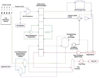
Carbon Capture using cryogenic method is a post-combustion technology designed to reduce carbon emissions from various industrial sources. There are several different configurations of the cryogenic carbon capture process. One notable process cools the gases to very low temperatures, specifically to the frost or desublimation point of CO2 (between -100°C and -135°C), to separate CO2 as a solid, as shown in the figure below.1 In this process, the CO2 is first separated from other gases and then pressurized. The solid CO2 is then warmed to produce a high-purity, pressurized CO2 stream.
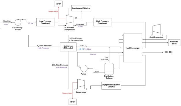
In another configuration, the CO2-containing stream is first compressed and then directed to a cold process. In this stage, CO2 is separated from other components of the feed gas and purified through partial condensation and distillation as shown in the figure below.2 Some of the impurities removed during the cryogenic process are recycled back to the plant's inlet. The final CO2 product is either compressed to the desired pressure (resulting in a gaseous or supercritical state) or recondensed and extracted as a liquid. This technology offers several benefits, including high CO2 recovery rates of up to 99%, CO2 purity levels exceeding 99%, and lower energy consumption compared to other carbon capture technologies. Additionally, it can remove other pollutants such as SOx, NOx, and mercury from flue gases. It applies to lower CO2 concentration point sources, as it can be integrated with other capture systems to increase CO2 concentration. However, the initial investment and operational costs can be high, although it aims to be more cost-effective than competing technologies. The information shown in this info sheet belongs mainly to the CRYOCAP™ technology from Air Liquide, as it is publicly available.3
TECHNICAL ASPECTS (all % are volume-based)
Point Sources: Steam-methane reforming, cement/lime, steel blast furnace, refineries, waste incineration/biomass power plant, pulp & paper, and iron and Steel.4
CO2 concentration range: 15-95%4
CO2 capture efficiency: 99%4
CO2 purity: 95%3 (CO2 pipeline standards)
Min. feed gas pressure: 1 bar2 (typical), 4 bar for Cryocap™ FG5
Max. feed gas temperature: 30 °C
Typical scale: Medium-large (> 100.000 tCO2/yr)6
Primary energy source: Electricity4
Impurity tolerance: High tolerance to common flue gas impurities, such as SOx and NOx. 6
FUNCTION IN CCU VALUE CHAIN
- Capture high-purity CO2 in liquid form.
- Removes impurities, eliminating the need for separate pretreatment steps (NOx and SOx).
LIMITATIONS
- High energy demand due to cryogenic cooling and compression.
- Capital-intensive equipment, such as refrigeration systems and heat exchangers.
- Pretreatment requirements for water and PM.
ENERGY
- Electricity is the main energy source.
- Cooling the flue gas is the most energy-intensive step.
- Integrated heat recovery enhances overall energy efficiency.
CONSUMABLES
- Refrigerants are used in a closed-loop system, minimizing loss.
| Parameter | Value |
|---|---|
|
Electricity (kWh/tCO2) Equation** |
FG: 410 5; H2: 320 6* Y= 660exp(-1.868X)7 667 – 1444 8 248 9*** |
|
* Cryocap™ FG and H2 ** Cryocap™: X – CO2 concentration and Y – electricity consumption *** Cryogenic carbon capture – gas to solid |
|
COSTS
CAPEX: 28 - 31 €/tCO2 10,11
15 €/tCO2 9
Main CAPEX: Cold box and compressors.
OPEX: 15 - 30 €/tCO2 11
8 €/tCO2 9
Main OPEX: Electricity
CO2 capture cost: 47 – 110 €/tCO2 8 (2021 euros)
Cryocap™ H₂: 30 – 50 €/tCO2 4 *
40 €/tCO2 for 50% CO2 11
Cryocap™ FG: 40 – 80 €/tCO2 4 *
48 €/tCO2 for 22% CO2 5
Cryocap™ STEEL: 25 – 60 €/tCO2 4 *
Cryocap™ OXY: 30 – 50 €/tCO2 4 *
Cryogenic carbon capture: 23 €/tCO2 9
CO2 avoidance cost: Cryocap™ H2: avoided CO2 cost reduction up to 40% compared to MDEA.4
Cryogenic carbon capture: 34 €/tCO2 9
* Ranges vary depending on CO2 concentration and the scale of operation.
10,11 Air Liquide’s Port-Jérôme; capacity - 100 ktCO2/yr; Cryocap™ H2; 2014 euros; CAPEX estimation with 30 yr lifetime; discount rate – 7%; electricity price - 60 €/MWh; supercritical CO2 product at 150 bar.
9 Cryogenic carbon capture; 2021 euros; capture efficiency – 90%; delivery pressure – 150 bar; electricity price – 74 €/MWh; avoidance cost includes transport and storage cost; NG as refrigerant.
ENVIRONMENTAL
CO2 footprint: 230 kgCO2eq/ton CO2 12,13
Spatial footprint: ~20,000 m2 per 0.9 MtCO2/yr 7 *
*Based on capture volume of 900 ktCO2/yr and 5 acres area.
Environmental issues: None, no by-product formation, solvent-free, no toxic or flammable gases used.
ENGINEERING
Maturity: FOAK Commercial system (TRL 8-9)4
Pilot plants and first commercial plants.
Retrofittability: Moderate4,11
This technology has a compact and flexible footprint to be retrofitted into existing industrial plants, contributing to a cost-effective solution.
Scalability: High
Well suited for a wide range of applications, allowing it to be adapted to different industrial settings due to its modularity.4
Process type: Cryogenic without solvents/sorbents and chemical reactions.
Deployment model: Only centralized. CO2 separation occurs only in the cold box.
Technology flexibility: Hybridizing with other CO2 capture technologies, such as PSA or membranes, is feasible. These technologies can be used to increase the CO2 concentration at the upstream.
TECHNOLOGY PROVIDERS
- Cryocap™ by Air Liquide, France
Cryocap™ H2: Capturing CO2 while boosting H2 production via steam-methane reforming (SMR)
Cryocap™ FG: Capturing CO2 from flue gases (cement plant), >=15% CO2 content
Cryocap™ STEEL: Capturing CO2 while boosting efficiency (steel plant), 20-50% CO2 content
Cryocap™ OXY: Capture and purification of Oxycombustion (NG/coal/biomass waste), >40% CO2 content
- Cryogenic Carbon Capture™ by Chart Industries, United States
- Cryogenic capture by Emicap, Belgium
- FrostCC™ by Carbon America, United States
INNOVATIONS
Emicap (Belgium) developed a technology also suitable for small-scale capture (<100 ktCO2/yr).
CONTACT INFO
Mohammed Khan (mohammednazeer.khan@vito.be)
Miet Van Dael (miet.vandael@vito.be)
ACKNOWLEDGEMENT
This infosheet was prepared as part of the MAP-IT CCU project funded by VLAIO (grant no. HBC.2023.0544).
REFERENCES
1. Baxter L, Hoeger C, Stitt K, Burt S, Baxter A. Cryogenic Carbon CaptureTM (CCC) Status Report. In: International Conference on Greenhouse Gas Control Technologies, GHGT-15. SSRN; 2021. Accessed February 20, 2025. https://ssrn.com/abstract=3819906
2. Spilman H. Overview of the CRYOCAP Studies.; 2015.
3. Air Liquide. CRYOCAP Carbon Capture Technologies. Published online 2021. efaidnbmnnnibpcajpcglclefindmkaj/https://impactclimate.mit.edu/wp-content/uploads/2022/08/CRYOCAPTechnicalSummary_HannahSpilman.pdf
4. Barlow H, Shahi SSM. State of the Art: CCS Technologies 2024.; 2024.
5. Rodrigues G, Raventos M, Dubettier R, Ruban S. Adsorption assisted cryogenic carbon capture: an alternate path to steam driven technologies to decrease cost and carbon footprint. 15th Greenh Gas Control Technol Conf 2021, GHGT 2021. 2021;(May).
6. Leclerc M, Rodrigues G, Dubettier R, Ruban S. Optimized configuration to reduce H2 carbon footprint in a refinery. 15th Greenh Gas Control Technol Conf 2021, GHGT 2021. 2021;(March).
7. NETL. Carbon Capture on Air Liquide US Gulf Coast Steam Methane Reformer Using CryocapTM FG Process.; 2024.
8. Font-Palma C, Cann D, Udemu C. Review of Cryogenic Carbon Capture Innovations and Their Potential Applications. C. 2021;7(3):58.
9. Hoeger C, Burt S, Baxter L. Cryogenic Carbon CaptureTM Technoeconomic Analysis. In: International Conference on Greenhouse Gas Control Technologies, GHGT-15. SSRN Electronic Journal; 2021:1-11.
10. Air Liquide. World premiere: Air Liquide inaugurates its CO₂ cold capture system, CryocapTM. November 5, 2015. Accessed February 20, 2025. https://www.airliquide.com/group/press-releases-news/2015-11-05/world-premiere-air-liquide-inaugurates-its-co2-cold-capture-system-cryocaptm
11. Terrien P, Lockwood F, Granados L, Morel T. CO2 capture from H2 plants: Implementation for EOR. Energy Procedia. 2014;63:7861-7866.
12. Cuéllar-Franca RM, Azapagic A. Carbon capture, storage and utilisation technologies: A critical analysis and comparison of their life cycle environmental impacts. J CO2 Util. 2015;9:82-102.
13. Khoo HH, Tan RBH. Life cycle investigation of CO2 recovery and sequestration. Environ Sci Technol. 2006;40(12):4016-4024.