Method diagram
Method diagram 1: Aerobic biofilter (trickling filter)
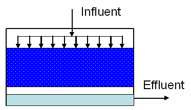
SOURCE: VITO-SCT, 2009
Method diagram 2: Aerobic biofilter (fluidised bed)
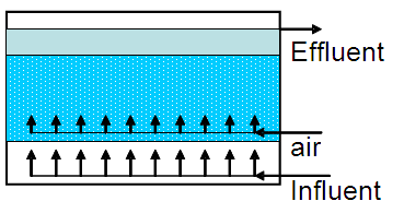
SOURCE: VITO-SCT, 2009
Method diagram 3: Biorotor
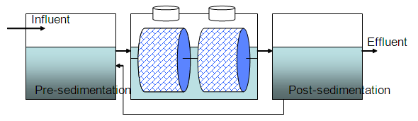
SOURCE: VITO-SCT, 2009
Method and installation description
The aim of sludge on carrier systems is to use micro organisms to remove COD via the biological degradation of organic components to CO2 and water. These micro-organisms are immobilised on a carrier system.
The biological processes for COD removal are similar to those in active sludge systems, though differ in terms of implementation method. Because the micro-organisms are immobilised on a carrier, there is no or very limited need for a sedimentation step.
Biofilter (see method diagram 1 and 2)
The theory behind a biofilter is based on the fact that micro-organisms are fixed on a carrier. The wastewater flows along the bio-film, which converts the pollutants. Sand, clay, lava or plastic (e.g. PUR) can be used as carrying material. The biofilter can be static or dynamic. A static biofilter contains carrier material in a tank or barrel. The wastewater will then pass through upwards or downwards. Typical examples include the static sand filter and the ‘trickling filter’. The latter involves filling a tank with carrier material (plastic rings or lava stones) and distributing water at the top of the filter. Aeration occurs via the contact between wastewater and surrounding air while the water passes through the filter. In the case of submerged biofilters, water is pumped from the bottom upwards. In a dynamic biofilter, the filter bed is continuously present. An example of this is the continuous sand filter, where the sand is continuously regenerated. Various fluidized biofilters (fluidized bed reactor) are also available, where sand, inert material or active carbon act as carrier material and create a fluidised bed thanks to a sufficiently high upflow speed. Anaerobic treatments on wastewater can be carried out with anaerobic biofilters.
Biorotor (see method diagram 3)
The biorotor is a unit with a drum as a frame, which contains a honey cone structure or a filling material on which micro organisms are immobilised. The drum is partly submerged into a container through which wastewater flows continuously, whereby the organic matter is adsorbed and converted. Aeration takes places via rotation and contact with the open air. The wastewater then flows into a post-sedimentation tank, where the sludge sinks. Bioreactors are also suitable for nitrification. Nitrifying micro-organisms grow slowly; these micro-organisms can survive effectively because of the immobilisation in a bioreactor. An extra denitrification step is needed for complete nitrogen removal.
Specific advantages and disadvantages
There are numerous carrier materials, each with specific advantages and disadvantages. The advantage of a synthetic carrier like PUR is the large specific area and the low weight. It is also a relatively cheap material.
Sludge on carrier systems are suitable for treating wastewaters with relatively low concentrations of COD and nitrogen (N). Trickling filter systems are also used as the first step in biological purification for the degradation of difficult to degrade components. Hydraulic peaks and high concentrations reduce the effluent quality in biofilters. One should also prevent the carrier material from becoming blocked. This can be done by subjecting the filter to an appropriate cleaning cycle (e.g. rinsing static sand filters).
Sludge on carrier systems have a low buffering capacity. Hydraulic peaks and high concentrations reduce the effluent quality. Almost no manual intervention is required.
Application
The biorotor is used for small-scale water purification on-location, at hotels, restaurants and camp sites, for example. Further, the biorotor is also used in the food sector and other industries.
Boundary conditions
Pre-sedimentation is sometimes needed because a sludge on carrier system can block quickly if a lot of suspended matter is present. Each system has specific boundary conditions.
Here are a few typical characteristics and statistics for biorotors:
- Material: Plastic, PVC, polyethene, styropor foam;
- Specific surface area rotor medium: 50 to 250 m²/m³;
- Ration tank volume/rotor surface area 0.004-0.01 m³/m²;
- BOD load: 5 to 40 g/m².d, decrease 60% to 90%;
- N-Kjeldahl load: 1 to 6 g/m².d, decrease 80% to 95%;
- Hydraulic retention time: 1 to 3 hours for BOD removal and 3 to 6 hours for N-Kjeldahl removal;
- Sludge production: 0.5 to 1.5 kg sludge per kg removed BOD.
Effectiveness
The removal of BOD and nitrogen is in excess of 90% on average, depending on the BOD/N ratio in the wastewater and the retention time in the sludge on the carrier system.
Support aids
If necessary, the pH of the wastewater must be corrected using lye or acid.
Nutrients such as N and P can sometimes be added to improve effectiveness.
Environmental issues
Sludge is released as by-product. Depending on the influent, the location and the system, it may be necessary to take measures against odour problems, the emission of harmful substances and aerosols into the air, and noise problems.
Costs
The investment cost for a biorotor with lamella separator for treating 10 m³/day with a COD of 2.500 mg/l amounts to approximately € 65.000 (case industrial wastewater from graphic sector - 2006).
The investment cost for a bioreactor for treating 6 m³/hour including buffer tank, pH correction, post-sedimentation tank and extraction and treatment of air from the biorotor in an active carbon filter, amounts to approximately €105.000 (case study industrial wastewater from graphic sector, 2006).
Comments
Nitrification normally requires nitrates to be further treated.
Complexity
A sludge on carrier system is a simple wastewater purification technique.
Level of automation
This wastewater purification system can be fully automated.
References
- EIPPCB, Reference Document on BAT in Common Waste Water and Waste Gas Treatment / Management Systems in the Chemical Sector, draft February 2009 (revision upon release)
- Environmental Technology, Monographs handbook, Envi Tech Consult, INC, Den Haag, Handbook on Wastewater
- Manual of Effluent Process Technology, Environmental & Process Engineering Department, AEA Technology, Harwell (GB), 1991
Version February 2010