Synonyms, abbreviations and/or process names
- Catalytic afterburning
Removed components
- VOC’s, odour
- Carbon monoxide
- Halogenated compounds (specific catalysts required)
- CO
- (Fine organic particles)
Diagram
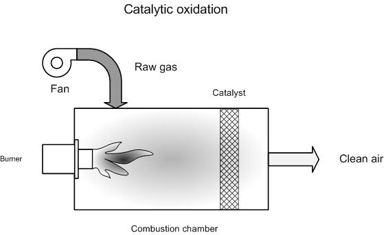
Process description
Catalytic afterburning works in a manner similar to thermal afterburning, with the difference being that the gas, after it has passed the flame, passes through a catalyst yet again. The catalyst ensures accelerated oxidation at lower temperatures. Thus afterburning can take place at lower temperatures.
The gas is heated to approximately 300 – 500 °C prior to the catalyst. The maximum gas temperature after the catalyst is typically 500 – 700 °C. New low temperature catalysts are able to operate at 200 – 250 °C.
Due to the lower temperature, the fuel required to achieve autothermicity is lower than that in thermal afterburning. This means that catalytic afterburning can be implemented at lower concentrations than thermal afterburning. Autothermicity is realised from 10 -12 g/m³ VOC [6]. According to BAT [7] this is 10 – 14 g/m³ VOC.
The used catalysts are typically precious metals (platinum, palladium, rhodium…) on a ceramic or metal carrier, base metals on a ceramic carrier or metal oxides on a strong mechanical carrier.
For chlorinated compounds, catalysts such as chrome, aluminium, cobalt oxide and copper oxide/manganese oxide are used. Platinum-based catalysts are suited to sulphur-laden components but are quickly deactivated in the presence of chlorine.
The presence of catalyst poisons or masking products, such as chemical substances and dust particles, can considerably reduce the life-span of the catalyst. Poisoning may be reversible. For example, this is the case if the catalyst surface is covered with fats and oils. These can be removed from the catalyst by increasing the temperature. Certain components can also irreversibly deactivate the catalyst.
Catalyst poisons include [1]:
- Fast-working poisons: Phosphorus, bismuth, arsenic, antimony, lead, mercury. They ensure permanent deactivation of the catalyst. The deactivation speed is determined by the concentration and the temperature.
- Slow-working poisons: Iron, tin, silicon. They also ensure permanent deactivation, but only at higher concentrations.
- Reversible inhibitors: Sulphur, halogens, zinc. Depending on the catalyst, a reversible layer is formed over the catalyst’s active area.
- Surface maskers: (organic) solids which form a layer over the catalyst surface. This leads to the catalyst’s active areas being covered.
- Erosive and masking components; inert particles: The level of erosion is determined by particle size, dust load and gas speed.
Recently, numerous catalysts have been developed that are more resistant to certain inhibitors. It is thus important to be well aware of gas compositions so that the correct catalysts can be selected and unexpected deactivation can be avoided.
Variants
There are two different systems for catalytic afterburning; namely, fixed bed and fluidised bed systems.
Fixed bed installation
Fixed bed installations can be set up with a structured catalyst or a packed bed. The structured catalyst consists of a monolithic material with the required air channels in the direction of the gas stream. The advantages of a structured catalyst are: Little wear on the material due to bed expansion and due to heating and cooling when started and stopped, and a low pressure drop. Packed bed catalysts consist of catalyst grains which have been added to a tube, plate or tray through which gases are passed. Compared to a structured catalyst, the pressure drop is greater and the catalyst can break when the catalyst-bed is periodically heated and cooled during start-up and shutdown.
Fluidised bed installation
In a fluidised bed, the air is passed upwards through the catalyst bed. Grains in the catalyst bed begin to move due to the high gas speeds, the bed expands and then starts to behave like a liquid. Fluidised-bed catalytic oxidation has the advantage of having better contact between pollutants in the air and the catalyst, thus there is better mass transfer and oxidation. The pressure drop is higher than that of structured catalysts. The fluidised bed also ensures better heat transfer. The third advantage is the tolerance towards dust. Fixed bed systems may become blocked or the catalyst surface may be covered, thus reducing activity. In a fluidised bed, the constant friction between grains ensures that the catalyst surface remains clear. The disadvantage of this is that, due to the constant abrasion, part of the catalyst is lost.
Recuperative and regenerative catalytic afterburning
Catalytic afterburning can be combined with energy recuperation. This energy recuperation can be either recuperative or regenerative. This is described in 'recuperative thermal oxidation' and 'regenerative thermal oxidation'.
Efficiency
The destruction yield for VOC’s is 95 - 99% depending on the type of catalyst, the operating temperature and size of the catalyst bed. To realise high yields, longer residence times – thus larger catalyst volumes – are needed. This increases the cost of the installation.
The destruction yield for odour is 80 – 95%.
The end concentration of VOC is less than 20 mgC/Nm³. This value can possibly be exceeded due to a greater methane emission [4]
CO is removed simultaneously with the VOC. In contrast to thermal afterburning, one should not work above a particular temperature. A typical end concentration is less than 50 mg/Nm³ CO [4].
Boundary conditions
The conditions for the application of catalytic afterburning are:
- Absence of catalyst poisons: An accurate and comprehensive analysis of flue gases would be desirable
- Limited dust-load: Depending on the set-up of the afterburner and the type of substance. Indicative guideline 3 mg/Nm³ dust as maximum [4]
As in thermal afterburning, the boundary limit of 25% LEL (lowest explosion limit) is also applicable for safety purposes.
Auxiliary materials
The catalyst will need to be replaced periodically. The replacement frequency is determined by:
- Presence of poisons
- Working schedule: A lot of heating-up and cooling-down can harm the catalyst’s structural integrity
- Type of catalyst
- Operating temperature
- Correct process regulation and protection against high temperatures
Environmental aspects
Little CO is released during catalytic afterburning. A typical end concentration is less than 50 mg/Nm³ [4].
Due to the low combustion temperature, the NOx concentration in flue gases will also be low. A typical end concentration is less than 50 mg/Nm³ if no nitrogen-laden components are present [4]. Otherwise, it will be higher [4].
Energy use
The energy use is lower than for thermal afterburning without energy recuperation. Energy use is determined by the hydrocarbon content in the to-be-treated gases.
The operational area for thermal afterburning, which helps to reduce extra fuel use, lies between 1 500 – 3 000 ppmv. For catalytic afterburning, the operational area stays more-or-less the same. As indicated, less fuel will be needed for catalytic afterburning compared to thermal afterburning.
Cost aspects
Investment
- 10 000 -80 000 EUR for 1 000 Nm³/h [1]
- 14 000 -58 000 USD for 1 000 Nm³/h [3]
- 10 000 - 40 000 EUR for 1 000 Nm³/h [6]
Operating costs
- Personnel costs: ca. 0.5 days per week [1]
- Operating costs: 2 800 to 21 000 USD per year for 1 000 Nm³/h [1.3]
- Costs for catalyst amount to 1.4 -16 EUR/ m³/h [7]
- Extra costs amount to 0.9 EUR/m³/h depending on VOC concentration [7]
- Catalyst replacement: 35 – 250 EUR/kg catalyst, depending on the type [5]. Catalyst quantity is determined by the type of VOC, VOC load, catalyst type and flue gas flow rate.
Examples
Spray drier case study [5]
- Flow rate: 1 200 Nm³/h
- Investment: 55 000 EUR:
Metal-processing industry case study [7]:
- Flow rate: 2 000 Nm³/h
- Investment: 54 000 EUR
Advantages and disadvantages
Advantages
- More compact than thermal oxidation
- Lower oxidation temperature, so less extra fuel is needed
- Low NOx production; approximately 20 – 30 % of the NOx in thermal afterburning
- CO is destroyed at the same time as other components.
- Highly consistent and reliable performance possible
- Due to the low temperature, less insulation is need compared to thermal afterburning.
- Lower risk of fire compared to thermal oxidation
Disadvantages
- Lower yield for VOC removal compared to thermal oxidation
- System is sensitive to changes in energy-content in the gas
- Risk of dioxin-forming in the presence of chlorinated compounds
- All catalysts are subject to catalyst poisons and polluting substances
- Dust must be removed before afterburning
- Deactivated catalysts cannot be regenerated, and are disposed of.
Applications
Catalytic oxidation is mainly used for the removal of VOC from solvent evaporation. A few implementation examples:
- Bulk-loading fuel stations;
- Production of organic chemicals;
- Production of rubber and polymers;
- Resin production;
- Application and drying of solvent-laden coatings.
- Destruction of ethylene oxide from sterilisation at 140 – 235 °C and an in-going concentration of 3000 ppm [10]
Catalytic oxidation is particularly suitable if the type and concentration of solvents remains relatively consistent and if no catalyst poisons are present. A specific area of implementation is the oxidation of carbon monoxide in catalysts for combustion engines.
References
- BREF: "Common waste water and waste gas treatment /management systems in the chemical sector" EIPPC, February 2002
- Factsheets on Air-emission reduction techniques, www.infomil.nl, Infomil
- EPA Air Pollution Technical factsheet: Catalytic incinerator
- VDI 2587 part 1: Emission control: heatset web offset presses, November 2001
- Supplier information
- A. Jacobs, B. Gielen, I. Van Tomme, Ch. De Roock and R. Dijkmans., Best Available Techniques for the wood processing industry, October 2003
- L. Goovaerts, M. De Bonte, P. Vercaemst and R. Dijkmans., Best Available Techniques for the metal processing industry, December 2003
- A. Derden, J. Schrijvers, M. Suijkerbuijk, A. Van de Meulebroecke1, P. Vercaemst and R. Dijkmans., Best Available Techniques for the slaughterhouse sector, June 2003
- J. Van Deynze, P. Vercaemst, P. Van den Steen and R. Dijkmans., Best Available Techniques for paint, varnish and printing ink production, 1998
- P. Vercaemst, A. Vandebroek, M. Hoessels, H. Witters and R. Dijkmans., Best Available Techniques for hospitals and other healthcare institutions, May 2003