Method diagram
Method and installation description
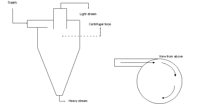
A hydrocyclone is often divided into 4 components.
- Inlet section: the inlet section consists of a cylindrical supply chamber into which the incoming supply flow enters. This supply flow is converted into a cyclone using a pump;
- Overflow section: light parts leave through the top of the hydrocyclone in this section;
- Conical section: this section consists of a cone-shaped surface where the liquid accelerates. This acceleration is caused by the angle and the geometrics of the conical surface and helps higher centrifugal forces to be developed.
- Tail section: This section is found at the bottom of the hydrocyclone and is aimed at extending the retention period for separation.
To summarise, a hydrocyclone separates particles using the generated centrifugal forces. This centrifugal force is generated because the liquid enters the cyclone tangentially at high speed and is accelerated by a conical middle section. This helps to create a liquid vortex in the cyclone. The smaller the diameter of the cyclone, the greater the centrifugal force that will be generated because the liquid is forced to take a sharp turn. Light components leave the hydrocyclone through the top, while heavier components are collected at the bottom.
Due to the presence of centrifugal forces, a hydrocyclone could be confused with a centrifuge. There are no moving parts in a hydrocyclone and the size of the centrifugal force is around 1000 times greater than gravity. A centrifuge is a dynamic device with moving parts whereby the generated centrifugal force is greater than that generated in a hydrocyclone.
In order to choose between a centrifuge and a hydrocyclone, one should consider the following:
- If the solid parts sink within 2 minutes when gravitational sedimentation is used, then a hydrocyclone is likely to be selected.
- If gravitational sedimentation takes longer than 2 minutes, then a centrifuge is likely to be selected.
Specific advantages and disadvantages
First and foremost, a hydrocyclone is a cheap and proven technique. There are no moving parts in this device, which makes construction easier. Depending on the application, cyclones can be made more compact whereby they take up less space. It is also possible to place multiple cyclones next to each other in a series or in a parallel set-up. Further, there is little need for support products.
The primary disadvantages of a cyclone are wear and tear of materials and the need to buffer the supply flow in order to create a consistent supply to the hydrocyclone.
Application
Hydrocyclones have a wide range of applications. They are primarily used as a separation technique.
- Separation of fine particles: Removal of large crystals in crystallisation systems;
- Removal of large particles; e.g. removal of waste from fruit juices;
- Preparing solutions or suspensions via controlled mixing of solid particles and water;
- Gravitational separation of organic material from sugar beet effluent;
- Separation of oil and water in oil refineries.
Boundary conditions
Suspended particles resistant against shearing forces, with a diameter between 5 and 1000 ?m and likely to sink, can be separated in a cyclone.
The separation capability when various hydrocyclones are compared is expressed as d50 cut-size. The d50 cut-size represents the minimum size of the particles that are at least 50% removed by the cyclone. These particles are then separated as slurry at the bottom of the cyclone.
The dry matter content in the slurry is between 1 and 10%. A hydrocyclone designed for a flow of 100 m³/hour takes up around 20 m².
Effectiveness
When crude oils are processed, cyclones are used to separate oil and water. In this application, oil droplets equal to or greater than 30 ?m can be separated to a removal efficiency of 98%.
Support products
No support products are used in this technique.
Environmental issues
Depending on the application, a layer of sludge will form at the bottom of the hydrocyclone, which must be disposed of or processed.
Costs
For a steel hydrocyclone system with standard instrumentation and for oil separation from an aqueous flow of 1000 m³/day, the investment costs amount to approximately 250,000 euros.
These costs only relate to investment costs concerning the hydrocyclone installation. They include required equipment like pumps, piping and sludge tanks. Other costs, like water pre-treatment, drainage, drying and electrical and mechanical installation costs have not been included.
Comments
A hydrocyclone should ideally feature a consistent supply of feed volume. The presence of long fibres in the liquid should be avoided when hydrocyclones are used.
Complexity
The process is easy to implement and the workings are not complex.
Level of automation
The process can only be automated using pump controls. This means it does not have a high level of automation.
References
- An., Development of Hydrocyclones for Use in Plastics Recycling, APC Hydrocyclone Separations Report, 1998
- Bradley, D., The hydrocyclone. Pergamon Press, New York, 1965
- EIPPCB, Reference Document on BAT in Common Waste Water and Waste Gas Treatment / Management Systems in the Chemical Sector, draft February 2009 (revision upon release)
- Mohanty M.K. et al., Minerals Engineering, 15 (2002), 727 – 736
- Pupraert C. et al., Chemical Engineering and Processing, 43 (2004), 67 – 83
- Wongsarivej P.et al., Separation and Purification Technology, 63 (2008), 452 – 459
- VITO-SCT, revision of technical files WASS, 2009
Version February 2010