Principle diagram
Principle and installation description
Electrodialysis is a membrane process that is used to remove ions from solutions.
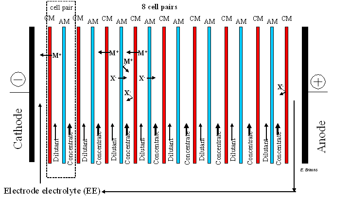
Alternating anion–selective membranes (AM) and cation-selective membranes are placed between the anode (+) and the cathode (-). Under the influence of an electric field, anions will migrate in the direction of the anode and cations with migrate in the direction of the cathode. Anions are stopped by the CM and the cations by the AM, which creates a process flow that continues to reduce in ions (the dilutant) and a process that continues to increase in ions (the concentrate).
A combination consisting of a CM, an Am and both areas between these membranes is referred to as a cell pair (see figure, indicated by dotted line). A cell pair is the basis unit of a stack, and is repeated n times (in the figure, n=8). In practice, a stack can contain hundreds of cell pairs.
There are two electrodes on the outer side of the stack of cell pairs (cathode and anode), which are submerged in an electrode electrolyte (EE). An electrolyte is a watery salt solution (split into ions) and is able to conduct electrical current. The EE allows an electrical field to be placed around the stack. The EE is pumped around (cathode ? anode? cathode) to retain the ion balance in the EE. Because salt solution (supply current) is also found between the membranes, the electrical field will result in ion transport, as shown in the figure. In the spaces between electrodes, marked as dilutant, the cations will diffuse through the CM to the negative electrode (cathode) while the anions will diffuse through the AM to the positive electrode (anode). The anions migrating from the dilutant chamber, as well as the cations, end up in the adjoining concentrate chamber. This results in a drop in concentration of cations and anions in the dilutant chambers during the ED process. In contrast, in the concentrate chambers, the cations will try to move to the negative electrode, although they are unable to diffuse through the AM. The anions in the concentrate chamber cannot migrate to the CM, towards the positive electrode, in an analogous manner. This results in an increase in the concentration of cations and anions in the concentrate chambers. Thus the dilutant chambers are de-salted while the concentration chambers gain in salt. It must be noted that the membrane stack must be closed using a membrane that is identical to the first membrane (e.g. to prevent Cl ions at the anode from being reduced to poisonous chlorine gas and to protect the EE from unwanted ions from the power supply).
Specific advantages and disadvantages
Each cell in an ED stack displays identical ion transport, whereby identical electrical current strength (current density) is realised in each cell. Thus the benefit of a stack is that total transport (desalting) is proportional to the number of cell pairs. A major drawback is that, as of a particular current density (the current density limit), the transport of ions is no longer linear to the implemented voltage (according to Ohm’s law) but levels off to a zone where water dissociation takes place (system is inefficient under these circumstances). So in the interest of energy-efficiency, one must always operate below the current density limit. Various experimental measuring procedures are available to determine the current density limit for a particular (waste) current or a specified Dilutant Out concentration.
The use of n cell pairs in a stack also has other advantages:
- The two electrodes are used for n cell pairs and thus electrode costs are relatively low. The electrode material is expensive because of the special materials (e.g. titanium).
- The energy loss due to over-voltage (over-potential) at the electrodes is negligible for high n.
- H+ and OH- reactions at electrodes only impact cell pairs located in close proximity.
- The total produced quantity of hydrogen and oxygen is limited at the electrodes.
However, a number of limitations must also be taken into account:
The voltage required for the electrodes is also proportional to the number of cell pairs. Thus one needs to consider voltage and current strength capacity when evaluating power supplies available on the market.
- In terms of hydraulics, the stack must also be designed so that equal distribution of concentrate is guaranteed for all cell pairs (more difficult with rising n).
Membrane pollution may also occur, but the EDR method (electrodialysis reversal) can help to largely avoid membrane pollution. In EDR, the voltage at the electrodes is reversed every 30 to 60 minutes, simultaneously with the dilutant and concentration flow. This reverses the direction of ion transport (thus also transport of pollutant substances), whereby the membrane is cleaned each time. Surface-active substances with polar groups may cause serious, perhaps irreparable, pollution to membranes. It is recommended to remove dispersed particles, colloids or humus acids in advance; sand filtration, cartridge filtration, micro filtration, ultra filtration, flocculation methods or active carbon can be used for specific removal. Oils and fats must also be removed (coagulation or active carbon). Regular membrane cleaning with specific cleaning products (acids, bases…) may be necessary in a number of cases. The average life-span of ED membranes is between 5 and 7 years.
Applications
ED has a wide range of applications:
- ED can be used to recover valuable electrolytes or acids from rinsing baths in metal (surface) treatments. ED can be used to perform pre-demineralisation in water supply for boilers. ED can be used to remove salts or to concentrate salt solutions (NaNO3…). It is also possible to convert salt into an acid or base (e.g. recovering acids from frosting baths). The aim is to also recover process water.
- ED is still being used to create drinking water from sea water or brackish water. As far as drinking water preparation is concerned, ED is also used to remove nitrate.
- In the food industry, ED is used to demineralise milk products or sugar-related solutions. The amount of acid in fruit juice can also be reduced. In Japan, ED (combined with vaporisation) is used to prepare cooking salt from sea water.
- Thus ED can be used in sectors where ions need to be removed from a process flow or must be concentrated (e.g. chemicals industry).
Boundary conditions
ED membranes must fulfil a number of conditions regarding sufficient selectivity and conductivity and sufficient mechanical strength. There are two types of ion conducting membranes. Homogenous membranes have a homogenous mass structure, whereby the ions are able to disperse through the entire structure. This is in contrast with inhomogeneous membranes, which consist of a synthetic matrix with ion-exchanging resin particles embedded into it. Homogenous membranes are more expensive but have much greater conductivity and strength. Inhomogeneous membranes are cheap but, in general, provide lower conductivity and strength (unless reinforced and/or unless a thicker membrane is used).
Effectiveness
ED can be implemented for removing the following parameters:
- Dissolved substances;
- nutrients (N and P);
- (heavy) metals;
- Inorganic salts.
Suitable ED process conditions can be determined experimentally, and designed software can be used to estimate the most appropriate stack configuration. ED is effective in a wide range of areas and ion removal can be implemented extensively. By taking into account the current density limit, this can be done via numerous ED steps (one step consists of an ED stack configuration which can be operated at a suitable lower current density, with a lower current density limit for lower concentrations).
Support substances
Please refer to the support substances needed for the above mentioned pre-treatment methods (e.g. flocculants and coagulants) and membrane cleaning methods (cleaning products).
Environmental aspects
As in most membrane separation technologies, two flows are created: A dilutant flow and a concentrate flow. If the concentrate flow is a waste flow (this is the case in a number of concentrate flows), this gives rise to problems when removing this waste flow if discharge is forbidden. One option is to treat this concentrate flow using a vaporisation technology, in order to arrive at a moveable/dry waste.
Costs
The major costs in ED are membrane and electricity costs. The current density limit is a limiting factor in ED, because this limit being reached is linked to the splitting of water, and thus results in energy loss. Thus, for all stacks in the installation, the activity must take place in the Ohm area (desalting linear with voltage). These stacks are normally in a series configuration and the last stack, with the lowest Dilutant Out concentration, is where the risk of limiting current density manifests itself. It is thus recommended to determine the limiting current density via experiments, and to use it in ED design software to determine the optimum (series) stack configuration (total length and total membrane surface). The limiting current density thus determines the price of the ED process: Therefore, it is not possible to provide a general price indication for ED, because ED design is, as a result of concentration specifications, fully determined by the specific application. As a general rule of thumb, in practice, a limit of 3000 ppm of dissolved substances is regarded as the limit between cost effective treatment via reverse osmosis and ED: Thus, ED if lower than 3000 ppm and reverse osmosis if above 3000 ppm. Another argument in favour of ED could be the need for high feed recovery. For an ED installation which treats 10 m3 of wastewater per day, originating from surface treatments in the metal industry, one should take into account an investment of 200 000 € and operational costs of 50 000 €/year. Cost prices may vary greatly depending on the type of wastewater.
Comments
There is little knowledge of full-scale implementations, with most installations being smaller in scale. Due to the specificity of each application, extensive testing will be needed for a full-scale implementation.
Complexity
For particular applications, an optimally-configured ED installation represents a robust working process. However, deeper insight is needed into complex ED parameters when modifying the boundary conditions of a particular application (concentration, volume…).
Level of automation
The ED installation has a robust structure: For a classic ED, one only needs three simple (separate) liquid circuits: The dilutant flow, the concentrate flow and the EE, for which volumes must be configured. Standard stacks are available with membranes appropriate for the required application. A standard electrical power supply is also available. For parameter optimisation, one can first run an ED pilot which contains specific instruments for following-up the process during the ED tests. Such instruments measure pressure, volume, temperature, pH and conductivity. Once conditions have been optimised for a particular application, an industrial installation can, in principle, operate independently without extensive instrumentation, once the optimised parameters have been set to within the process limits. In this regard, an ED installation offers a fairly high operational certainty if (incidental) membrane pollution is prevented.
References
- AEA Technology, Manual of Effluent Process Technology, Environmental & Process Engineering Department, Harwell (GB), 1991
- Davis T.A., Genders J.D., Pletcher D., A First Course in Ion Permeable Membranes, Alresford Press, England, ISBN 0 9517307 8 9, 1997
- European Desalination Society (www.edsoc.com), Course on Electromembrane Processes: their principle and practical application, March 26-27, 2007, L’Aquila, Italy, 2007
- Kemperman A.J.B., Handbook on Bipolar Membrane Technology, Prepared within the framework of the ‘Thematic Network on Electro-Membrane Processes’,
- Krol J.J., Monopolar and Bipolar Ion Exchange Membranes, PhD exam entry, Twente University, 29 August 1997
- Mulder M., Basic Principles of Membrane Technology, Kluwer Academic Publishers, Dordrecht (NL), 1996.
- Dutch Membrane Guide, The range of technical membranes in the Netherlands and Belgium, version 2.0, February 1996, Netherlands, ISBN number 90-74718-04-3, 1996
- Sata T., Ion Exchange Membranes: Preparation, Characterization, Modification and Application, Royal Society of Chemistry, London 2004
- Strathmann H., Ion-Exchange Membrane Separation Processes, Elsevier, New York, 2004
- TNAV, supplier survey, 2008
- Twente University Press, Enschede, ISBN 9036515203,2000
- Visser C.R., Electrodialytic Recovery of Acids and Bases, PhD exam entry, University of Groningen, 2 February 2001
- VITO-SCT, review of technical files WASS, 2008
- Wilson J.R., Demineralization by Electrodialysis, Butterworths Scientific Publications, London, 1960
Version February 2010