Synonyms, abbreviations and/or process names
- Thermal oxidation
Removed components
- VOC
- Odour
- Halogenated organic compounds
- CO
- (Fine organic particles)
Diagram
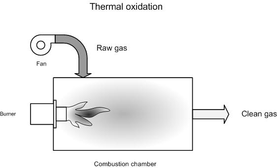
Process description
Flue gases, along with the required quantity of combustion air, are brought to a high temperature. In thermal after burning, this temperature varies between 750 and 1 200 °C. The gases are kept at this high temperature for a long enough period of time, whereby pollutants (VOC, odour…) are oxidised with oxygen into CO2, H2O, N2, SOx, HCl… .
The efficiency of afterburning is influenced by the temperature, residence time, turbulence (for mixing) and available oxygen.
For classic VOC’s a combustion temperature between 750 and 1000 °C is sufficient. For environmentally-harmful and halogenated components, an afterburning temperature between 1 000 °C and 1 200 °C is recommended in order to ensure that these components are destroyed.
Destruction takes place quicker at higher temperatures than at lower temperatures. This can be exploited when deciding the size of the combustion chamber. A large combustion chamber with a low temperature has higher investment costs but lower fuel costs. A smaller combustion chamber at a high temperature will have the same yield, though lower investment costs and higher fuel costs.
Heat is released when organic components in flue gases are oxidised. If the concentration of VOC's is high enough, the released heat is sufficient to maintain the process temperature, thus allowing afterburning to take place autothermally. For combustion temperatures of 750 – 1000 °C [8], the autothermal point lies between 20 – 22 g VOC/Nm³. In BAT [9] an autothermal point between 20 – 24 g/m³ has been indicated.
From an economic perspective, the inlet concentration should be between 1 500 and 3 000 ppmv, which limits the use of support fuels. For VOC concentrations that are too low, one must add extra fuel to afterburn the gases. For thermal afterburning, support fuels normally account for the largest variable cost.
Variants
Injection into an existing boiler
As a variation to classic thermal afterburning, flue gases can be oxidised in an existing boiler. This is only possible if the volume of the flue gas stream is low enough and if no corrosive gases are present or no corrosive combustion products are formed.
In practice, the boiler manufacturer will need to be consulted to ensure that the boiler has not been damaged and to discover whether the supplier’s guarantee and liability are still applicable.
For injection into an existing boiler, it is preferable to inject gases into the boiler simultaneously with combustion air and not through the side of the combustion chamber. In the latter case, there is a considerable chance of dead streams, whereby the yield could be reduced to an insufficient level.
One could use various methods to more quickly realise autothermicity:
- Use of regenerative adsorption. The advantages are a smaller gas stream and a higher hydrocarbon content. See ‘regenerative adsorption’
- Use of heat recuperation via heat exchanger: See 'recuperative thermal oxidation’
- Use of regenerative beds to pre-heat air: See 'regenerative thermal oxidation’
Efficiency
The VOC removal percentage typically amounts to 98 – 99.9 %. If long residence times and higher temperatures are used, purification can take place with a yield in excess of 99.9%. This is sometimes implemented for halogenated compounds.
End VOC concentrations of < 1 – 20 mg/ Nm³ are attainable with a minimum end oxygen content greater than 3 vol%. In afterburning installations end oxygen concentrations are typically 16 – 20 vol% O2, so no problems are encountered.
CO can also be oxidised with afterburners. CO is more difficult to oxidise than VOC due to the high ignition temperature (609 °C). Table 1 shows CO removal efficiency with a minimum O2 concentration after afterburning of 3% , as a boundary condition [4].
Table: CO removal efficiency in function of temperature [4]
|
Temperature (°C) |
Removal efficiency (%) |
|
760 |
78 |
|
788 |
85 |
|
816 |
91 |
|
843 |
95 |
|
871 |
98 |
|
899 |
>99 |
Boundary conditions
- In the interest of safety, the hydrocarbon concentration in the flue gas mix must be kept below 25% of the lowest explosion limit (LEL).
- Dust concentrations should be less than 3 mg/m³. In specific applications for burning organic matter, this can higher [7].
- Particularly suited to higher VOC concentrations (5 – 16 g/Nm³) [9]
Auxiliary materials
No auxiliary materials
Environmental aspects
When VOC’s and the support fuel are burnt, CO2 is released - which is a greenhouse gas.
Besides CO2, CO and NOx are also formed. The formation of large quantities of CO and NOx can be avoided via
effective process regulation.
- CO
Specifically for CO, E. Donley [4] states that realisable CO concentrations are greatly determined by the combustion temperature. Under a temperature of 870 °C, CO emission rises exponentially. If the temperature falls from 870 to 760 °C, the specific CO emission per kg oxidised VOC is multiplied by 5. Absolute figures have not been mentioned.
According to Uberoi H. [5] CO concentration in afterburning increases to a maximum at 650 °C. CO concentration falls sharply above this temperature. CO emission is relatively low around 760 °C. A temperature window of 750 – 815 °C has been proposed to restrict CO concentrations.
According to Martin K. [6] CO bonds break at 760 °C. To ensure effective destruction of CO bonds in VOC’s, a residence time of 0.3 seconds at 760 – 815 °C is needed. For CO at the same temperature, a residence time of 0.4 seconds is required.
- NOx
NOx emissions amount to less than 100 mg/Nm³ in an afterburner with natural gas as support fuel, and with no nitrogen components present in flue gases [7].
- HCl, HF, SO2
In the afterburning of halogens and sulphur-laden compounds, HC1, HF, SO2… are formed. These must be removed via a treatment for acidic gases (dry lime injection, semi-dry lime injection, alkaline scrubber and wet lime srcubbing).
- Dioxins
One should also consider possible dioxin-forming when afterburning halogenated compounds. Dioxins (and other halogenated compounds in the chimney) can be avoided by operating at high combustion temperatures (1000 – 1100 °C) and longer residence times (minimum 1 second) so that existing dioxins are destroyed. The formation of dioxins from burnt gases can be avoided by removing precursors such as dust and heavy metals in advance, and by keeping the residence time of gas, in the temperature window of 400 °C to 200 °C, as short as possible. If dioxin-forming still takes place, this must be removed via activated carbon sorption.
Energy use
A support fuel is needed to keep combustion autothermic. Energy use is determined by the VOC content in flue gases.
Heat is also released when organic components in flue gases are oxidised. If the concentration of VOC's is high enough, the released heat is sufficient to maintain the process temperature, thus allowing afterburning to take place autothermally.
Cost aspects
- Investment
- Operating costs
- Personnel costs: ca. 0.5 days per week
- Auxiliary and residual materials: 24 000 to 45 000 USD per year for 1 000 Nm³/h [3]
- Energy costs: Greatly determined by the hydrocarbon content in flue gases (see energy use)
Examples
Case study: Hydrogeneration of edible oils [6]
- Flow rate: 200 Nm³/h
- Investment costs: 85 000 EUR
Thermal afterburner for flow rates up to 2 000 Nm³/h [6]
- Investment cost of 150 000 EUR
Advantages and disadvantages
Advantages
- Proven technology for hydrocarbons
- High efficiencies attainable, with yields up to 99.9999 %
- Good for high VOC concentrations: > 20 % LEL
Disadvantages
- High variable costs for fuels with low VOC concentrations
- Not well suited to variable flow rates
- Formation of corrosive acidic gases when halogen and sulphur-laden components are burnt.
- Not cost-effective for low concentrations and high flow rates.
- Regenerative and recuperative afterburing are normally better suited, due to reduced fuel costs resulting from energy recuperation
Applications
Compared to other afterburning techniques, thermal afterburning without energy recuperation is primarily suited to:
- Low flue gas volumes (< 860 m³/h)
- High loads where spontaneous combustion may occur in recuperative afterburning
- High flue gas temperatures, so little additional heating is required
- Flue gases with strong dust pollution, which could block the catalyst in catalytic afterburning and the heat recuperation installation in recuperative afterburning.
However, afterburning with energy recuperation is given preference if the above mentioned problems with heat recuperation are not encountered.
Indirect drying of industrial sludges is one application where injecting into an existing boiler is used. After condensation and acid scrubbing of dry vapours, a small volume of heavy odour-laden non-condensable gases is left over. These gases are injected into the boiler, together with the combustion air. The energy content of these flue gases is thus recuperated prior to sludge-drying.
References
- BREF: "Common waste water and waste gas treatment /management systems in the chemical sector" EIPPC, February 2002
- Factsheets on Air-emission reduction techniques, www.infomil.nl, Infomil
- EPA Air Pollution Technical factsheet: Thermal incinerator
- Donley, E and Lewandowsti, D: Optimised design and operating parameters for minimising emissions during VOC thermal destruction, presented at 88 the annual meeting of the Air & Waste management Association, San Antonio, Texas, 18 – 23 June 1995
- Uberoi M. Choosing the right VOC Emission Control Technology, International Environmental technology articles, vol. 9 issue 5 September /October 1999
- Martin K measuring, monitoring and controlling emissions by Marin Key Megtec Systems AB
- VDI 2587 part 1: Emission control: heatset web offset presses, November 2001
- A. Jacobs, B. Gielen, I. Van Tomme, Ch. De Roock and R. Dijkmans., Best Available Techniques for the wood processing industry, October 2003
- L. Goovaerts, M. De Bonte, P. Vercaemst and R. Dijkmans., Best Available Techniques for the metal processing industry, December 2003
- A. Derden, J. Schrijvers, M. Suijkerbuijk, A. Van de Meulebroecke1, P. Vercaemst and R. Dijkmans., Best Available Techniques for the slaughterhouse sector, June 2003
- J. Van Deynze, P. Vercaemst, P. Van den Steen and R. Dijkmans., Best Available Techniques for paint, varnish and printing ink production, 1998