DESCRIPTION
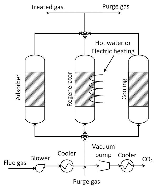
Feed gas is sent to the adsorber (adsorption) operating at atmospheric pressure. The CO2 adheres to the adsorbent while the other gas components pass through. The existing free gas is evacuated from the column using an evacuation pump. In the third step, the CO2 is desorbed in a countercurrent mode by applying a vacuum, followed by heat supply either through indirect heating using a working fluid (hot water) or direct heating using an electric supply.1 The application of vacuum allows for low-quality heat (waste heat) utilization, reducing the energy consumption. Similarly, a cooling step may be required either indirectly through working fluid (cooling water) or directly cooling using purge gas. The column is then pressurized with the feed gas for the next adsorption cycle.
TECHNICAL ASPECTS (all % are volume-based)
Point sources:
Pulp & paper, biomass, oil & gas, steam-methane reforming, lime, steel, cement, petrochemicals.2
Direct air capture – all values in parentheses below belong to DAC.3
CO2 concentration range: 10%-20%2,4 (400 ppm3)
CO2 capture efficiency: > 90%2 (70%5)
CO2 purity: > 95%2 (98.5 - 99.9%3)
Min. feed gas pressure: 1.1 bar4 (fan to overcome pressure drop3)
Max. feed gas temperature: 50 °C4 (40 – 50 °C6)
Typical scale: Small to Large (same for DAC7)
Primary energy source: Heat (direct or indirect by working fluid) and electricity for the vacuum pump.
Impurity tolerance: SOx = 1.5 ppm8; PM = 0.2 mg/m3 (assuming same as TSA). None required for DAC.
FUNCTION IN CCU VALUE CHAIN
- Capture CO2 from flue gases (or) directly from air.
- Adsorbents such as zeolites are highly affected by the presence of water in feed gas, requiring an upstream dehydration step in PSC.9 No such dehydration step is used in DAC.
- Highly affected by flue gas impurities in PSC, such as SOx and NOx, requiring appropriate pre-treatment steps.9 No such pre-treatment steps are used in DAC.
LIMITATIONS
- Adsorbent material may degrade over time due to thermal cycling and exposure to impurities in the flue gas, reducing overall capture efficiency.
- Maintaining a vacuum system adds complexity to the operation. The vacuum pumps and associated equipment require regular maintenance and can be a source of operational issues.
ENERGY
- Electricity is used by the blower at the upstream to be needed to overcome the pressure drop in the column in PSC.
- Electricity is consumed by the fans to direct the air to the DAC contactor and also by the control systems.3
- Electricity is consumed by the evacuation and vacuum pump to remove free gas and desorb CO2, respectively, in both PSC and DAC.
- Either low-grade/waste heat or electricity is used to complete CO2 desorption in both PSC and DAC.
CONSUMABLES
- Hot water could be used as a working fluid during CO2 desorption, but it can be reused.
- Cooling water may be required to cool the feed gas after the blower and cool the desorbed CO2 after the vacuum pump.
- No chemicals/solvents are used.
| Parameter | PSC | DAC |
|---|---|---|
| Electricity (kWh/tCO2) |
90 10 a 81 b |
200 – 300 3 c 150 – 260 3 d |
| Heat (GJ/tCO2) |
2.9 10 a 5.0 b |
5.4 – 7.2 3 c 4.2 – 5.1 3 d |
| Cooling water makeup (t/tCO2) |
-NA- 12.8 b |
0.1 7 |
| Adsorbent (t/tCO2) |
-NA- 0.0015 b |
0.003 7 |
|
a 13X adsorbent; feed pressure 1.5 bar; vacuum pressure 0.1 bar; 15% CO2 in dry gas; cycle time 4000 s; CO2 purity 97%. b VITO study; indirect heating using hot water at 90 °C; NGCC plant - 4% CO2; 360,000 tCO2/yr; adsorbent working capacity – 0.06 gCO2/g-sorbent; CO2 purity – 70%; CO2 capture efficiency – 75%. c Climeworks: amine-based adsorbent; indirect heat at 100 °C; Pvac – 0.2 bar; full cycle – 4 to 6 hrs.3 d Global Thermostat: amino polymer adsorbent; direct steam at 85-95 °C; Pvac – 0.5-0.9 bar; full cycle – 0.5 hrs.3 |
||
COSTS
CO2 capture costs of PSC
CAPEX: 8.5 €/tCO2*
Main CAPEX: adsorption columns and vacuum pump
OPEX: 77.5 €/tCO2*
Main OPEX: cooling water, electricity, and adsorbent
CO2 capture cost: 90 €/tCO2* (71% adsorbent cost)
Depends on adsorbent price, scale, CO2 concentration, and purity requirements.
* VITO study; indirect heating using hot water; free waste heat at 90 °C; NGCC plant – 4% CO2; capture capacity – 360,000 tCO2/yr; CO2 purity – 70%; CO2 capture efficiency – 75%; WACC – 4.6%; lifetime – 25 yrs; 2022 euros; electricity – 80 €/MWh; sorbent – 40 €/kg; adsorbent working capacity – 0.06 gCO2/g-sorbent; cooling water – 0.3 €/m3; fixed OPEX – 5% of CAPEX; operating hours – 8000 hr/yr.
CO2 capture cost of DAC
- €800 in 2023, €400-€700 by 2030 and €100-€300 by 2050 per tonne CO2 estimated by Climeworks.7
(no financial assumptions are provided)
- €220 per tonne CO2 in 2020
Capacity – 360,000 tCO2/yr; lifetime – 20 yrs; electricity – 250 kWh/tCO2 at 103 €/MWh; heat – 1750 kWh/tCO2 at 51 €/MWh by heat pump.
Depends on scale, specific energy consumption, and energy prices.
CO2 avoidance cost: Not available.
ENVIRONMENTAL
CO2 footprint:
PSC - 273 kgCO2eq/tCO2 captured 11
(assumed same as TSA; Estimate includes footprint (scope 1-3) for CO2 capture plant, compression, and conditioning.
DAC - 15-45 kgCO2eq/tCO2 captured 12
(Net footprint = Capture CO2 from air – CO2 footprint from energy consumption)
Spatial footprint:
PSC - 74,420 m2 (305x244) for 1.6 MtCO2/yr 4
(assumed same as TSA, additional footprint required for main and evacuation vacuum pumps)
DAC – 220 acres for 1 MtCO2/yr 7
Environmental issues: Disposal or recycling of spent adsorbents.7,13
ENGINEERING
Maturity:
PSC - Pilot (TRL 7)14
A pilot plant tested for a waste combustion plant.
DAC - Demonstration (TRL 7-8)7
Demonstration plants have been developed.
Retrofittability: Feasible
Heat and electricity are the main energy sources; phased implementation due to modular nature; handles flue gas impurities depending upon the adsorbent used.
Challenges due to large spatial footprint requirement.
Scalability: High2
Well-suited for capturing CO2 at a wide capture rate range due to its modular nature.2
Process type: Solid stationary adsorbent-based without chemical reactions.
Deployment model: Centralized only.
Each column with adsorbent undergoes cyclical CO2 adsorption and desorption.
Technology flexibility: Hybridization with other capture technologies is feasible. It can be used to increase CO2 concentration.
MAIN TECHNOLOGY PROVIDERS
PSC
- KCC system by Kawasaki, Japan (direct regeneration by steam at 60°C and 0.2 bar)
- CSAR by SINTEF and Caox, Norway. (uses heat and vacuum pumps)
- VeloxoTherm™ by Svante Inc, Canada. (same as TSA but with a vacuum; CALF-20 MOF; 8-25% CO2 concentration in flue gas)
DAC
- Direct Air Capture by Climeworks, Switzerland.
- Direct Air Capture by Global Thermostat, USA.
- Direct Air Capture by Skytree, The Netherlands.
- Direct Air Capture by Kawasaki, Japan.
- Metal Organic Frameworks for DAC by Mosaic Materials, USA.
- More DAC companies here.15
CONTACT INFO
Mohammed Khan (mohammednazeer.khan@vito.be)
Miet Van Dael (miet.vandael@vito.be)
ACKNOWLEDGEMENT
This infosheet was prepared as part of the MAP-IT CCU project funded by VLAIO (grant no. HBC.2023.0544).
REFERENCES
1. Gholami M, Van Assche TR, Denayer JF. Temperature vacuum swing, a combined adsorption cycle for carbon capture. Curr Opin Chem Eng. 2023;39:100891.
2. Barlow H, Shahi SSM. State of the Art: CCS Technologies 2024.; 2024.
3. Fasihi M, Efimova O, Breyer C. Techno-economic assessment of CO2 direct air capture plants. J Clean Prod. 2019;224:957-980.
4. Jelen D. Lh Co2Ment Colorado Project Final Report.; 2023.
5. Gebald C, Platkowski N, Ruesch T, Wurzbacher JA. Low-Pressure Drop Structure of Particle Adsorbent Bed for Adsorption Gas Separation Process. March 17, 2016.
6. Wiegner JF, Grimm A, Weimann L, Gazzani M. Optimal Design and Operation of Solid Sorbent Direct Air Capture Processes at Varying Ambient Conditions. Ind Eng Chem Res. 2022;61(34):12649-12667.
7. Webb P, Muslemani H, Fulton M, Curson N. Scaling Direct Air Capture (DAC): A Moonshot or the Sky’s the Limit?; 2023.
8. Ghaffari-Nik O, Mariac L, Liu A, Henkel B, Marx S, Hovington P. Rapid Cycle Temperature Swing Adsorption Process Using Solid Structured Sorbent for CO2 capture from Cement Flue Gas. In: Proceedings of the 16th Greenhouse Gas Control Technologies Conference (GHGT-16). GHGT-15; 2022:1-11.
9. Zhang J, Xiao P, Li G, Webley PA. Effect of flue gas impurities on CO2 capture performance from flue gas at coal-fired power stations by vacuum swing adsorption. Energy Procedia. 2009;1(1):1115-1122.
10. Jiang N, Shen Y, Liu B, et al. CO2 capture from dry flue gas by means of VPSA, TSA and TVSA. J CO2 Util. 2020;35:153-168.
11. Shah M, Haley J, Hassan N, et al. Engineering Study of Svante’s Solid Sorbent Post-Combustion CO2 Capture Technology at a Linde Steam Methane Reforming H2 Plant.; 2023.
12. Deutz S, Bardow A. Life-cycle assessment of an industrial direct air capture process based on temperature–vacuum swing adsorption. Nat Energy. 2021;6(2):203-213.
13. De Coninck H, Benson SM. Carbon dioxide capture and storage: Issues and prospects. Annu Rev Environ Resour. 2014;39:243-270.
14. Tveten SG. New technology makes carbon capture easier - SINTEF. Norwegian SciTech News. November 6, 2024
15. Faber G. Direct Air Capture: Definition and Company Analysis.; 2025.