DESCRIPTION
TECHNICAL ASPECTS (all % are volume-based)
Point sources: Biomass/MSW-based applications, coal-based plants, IGCC, chemical plants, ammonia, and H2 production.5
CO2 concentration range: 20% – 30%5
CO2 capture efficiency: 99%5
CO2 purity: 95%5
Min. feed gas pressure: 20 bar6
Max. feed gas temperature: 35 °C7
Typical scale: Medium to large (0.36 – 3.6 MtCO2/yr)5
Primary energy source: Electricity5
Impurity tolerance: Solvent is chemically stable and does not form heat-stable salts when in contact with the flue gas.8
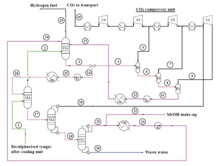
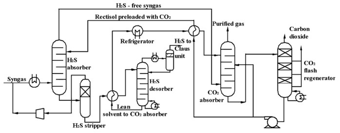
FUNCTION IN CCU VALUE CHAIN
- Capture CO2 from feed gases.
- Removal of other acid gases (e.g., H2S, COS).5
LIMITATIONS
- High energy requirements due to low operating temperatures.
- Less suitable for low CO2 concentration ranges.5
- Requires substantial refrigeration infrastructure.
- Higher selectivity for H2S over CO2.
ENERGY
- Electricity is primarily used for cooling and compression of the gas streams.
- Electricity is used in pumping solvent and refrigeration.
CONSUMABLES
- Methanol for solvent preparation, minimal loss due to regeneration, and make-up is required.
| Parameter | Value |
|---|---|
| Heat (GJ/tCO2) | 0.352 |
| Electricity (kWh/tCO2) | 402 - 831 |
| Cooling duty (GJ/tCO2) ** | 0.0812 |
| Solvent make-up (kg/tCO2) | 4.71 |
|
1 CO2 removal only, flash based; flow rate: 180.4 t/h; inlet pressure:27.9 bar; inlet temperature: 6.6 °C; outlet pressure: 110 bar; outlet temperature: 30 °C; ~90% energy is for compression; ~10% energy is for pumps; no heat duty required. 2 IGCC plant; 2-stage Rectisol; CO2 and H2S removal; feed pressure – 32.3 bar; ~40% CO2; 179 t/h CO2; 90% capture efficiency. ** Cooling duty refers to the refrigeration. |
|
COSTS
CAPEX: 9 €/tCO2 1
Main CAPEX: absorption column, cooling and refrigeration, pumps, and compressors.
OPEX: 38 €/tCO2 1
Main OPEX: electricity and maintenance.
CO2 capture cost: 47 €/tCO2 1
1 Rectisol process; IGCC plant; CO2 conc. – 38.6%; capacity – 1 MtCO2/yr; lifetime – 25 yrs; discount rate – 8%; 2015 euros; includes CO2 compression to 110 bar; electricity price – 96 €/MWh.
CO2 avoidance cost: 67 €/tCO2 avoided 9
9 Rectisol process; IGCC plant; CO2 & H2S capture; CO2 conc. – 39.85%; feed pressure – 32.3 bar; capture efficiency – 95%; capacity - 2 MtCO2/yr; lifetime – 35 yrs; fixed charge factor – 17.21%; 2014 euros; includes CO2 compression to 120 bar; electricity price – 142 €/MWh.
ENVIRONMENTAL
CO2 footprint: 294 kgCO2eq/tCO2 10,11*
26 kgCO2eq/tCO2 10,11**
*Emissions considered for materials and energy; includes IGCC plant, CO2 capture, liquefaction, transport, and storage.
**Emissions only for capture and liquefaction.
Spatial footprint: Not available.
Environmental issues: Minimal process emissions and effluents.
ENGINEERING
Maturity: Commercial (TRL 9)5
Commercial-scale Rectisol® units are operated worldwide.
Retrofittability: Moderate
Relatively retrofittable into facilities that already have syngas or gas processing units, but it requires significant cooling and infrastructure.
Scalability: High
The Rectisol process can be adapted to various capacities (modular system).5
Process type: Liquid solvent-based without chemical reactions.
Deployment model: Centralized or Decentralized.
Decentralized CO2 absorption at point sources with centralized desorption.
Technology flexibility: Hybridization with other capture technologies is feasible. Other technologies, such as membranes or PSA, can be used to increase CO2 concentration.
TECHNOLOGY PROVIDERS
INNOVATIONS
Recticap™ is an enhanced version of Rectisol™ specifically designed for energy transition projects focused on low-carbon hydrogen production.
Multi-stage Rectisol process for improved selectivity and higher CO2 capture rates.
BENCHMARK
- Amine-based absorption methods like MEA processes (chemical absorption).
- High-temperature physical absorption, such as Selexol.
CONTACT INFO
Mohammed Khan (mohammednazeer.khan@vito.be)
Miet Van Dael (miet.vandael@vito.be)
ACKNOWLEDGEMENT
This infosheet was prepared as part of the MAP-IT CCU project funded by VLAIO (grant no. HBC.2023.0544).
REFERENCES
1. Roussanaly S, Vitvarova M, Anantharaman R, et al. Techno-economic comparison of three technologies for pre-combustion CO2 capture from a lignite-fired IGCC. Front Chem Sci Eng. 2020;14(3):436-452.
2. Padurean A, Cormos CC, Agachi PS. Pre-combustion carbon dioxide capture by gas-liquid absorption for Integrated Gasification Combined Cycle power plants. Int J Greenh Gas Control. 2012;7:1-11.
3. Liu K, Song C, Subramani V. Hydrogen and Syngas Production and Purification Technologies. (Liu K, Song C, Subramani V, eds.). John Wiley & Sons, Inc.; 2010.
4. Ma Y, Liao Y, Su Y, et al. Comparative investigation of different CO2 capture technologies for coal to ethylene glycol process. Processes. 2021;9(2):1-19.
5. Barlow H, Shahi SSM. State of the Art: CCS Technologies 2024.; 2024.
6. Kohl AL, Nielsen R. Gas Purification. 5th ed. Gulf Pub; 1997.
7. Wang J, Shen Y, Zhang D, Tang Z, Li W. Integrated VPSA and Rectisol Process for CO2 Capture from UCG Syngas. SSRN Electron J. Published online 2022.
8. Zaman M, Lee JH. Carbon capture from stationary power generation sources: A review of the current status of the technologies. Korean J Chem Eng. 2013;30(8):1497-1526.
9. Porter RTJ, Fairweather M, Kolster C, Mac Dowell N, Shah N, Woolley RM. Cost and performance of some carbon capture technology options for producing different quality CO2 product streams. Int J Greenh Gas Control. 2017;57:185-195.
10. Cuéllar-Franca RM, Azapagic A. Carbon capture, storage and utilisation technologies: A critical analysis and comparison of their life cycle environmental impacts. J CO2 Util. 2015;9:82-102.
11. Viebahn P, Nitsch J, Fischedick M, et al. Comparison of carbon capture and storage with renewable energy technologies regarding structural, economic, and ecological aspects in Germany. Int J Greenh Gas Control. 2007;1(1):121-133.