DESCRIPTION
TECHNICAL ASPECTS (all % are volume-based)
Point sources: Power generation, Cement production, Refineries, Iron and steel, Process heaters, Combined heat and power.
CO2 concentration range: 3 – 25%
CO2 capture efficiency: > 90%
CO2 purity: >98%
(possible but not confirmed experimentally yet)
Min. feed gas pressure: 1.2 bar
(compressor required if lower than the above pressure)
Max. feed gas temperature: 40 °C
Typical scale: Small to Large (10 - 1000 ktCO2/yr)
Primary energy source: Heat (steam)
Impurity tolerance: Not available.
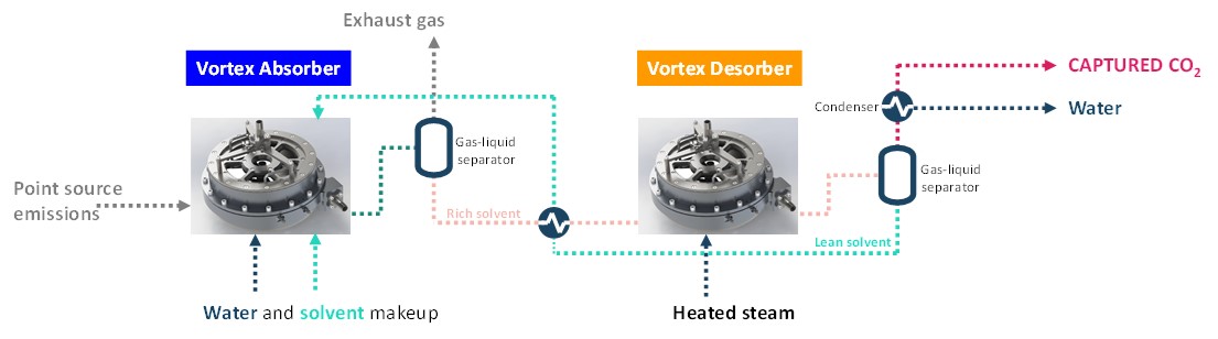
FUNCTION IN CCU VALUE CHAIN
- Capture CO2 from flue gases.
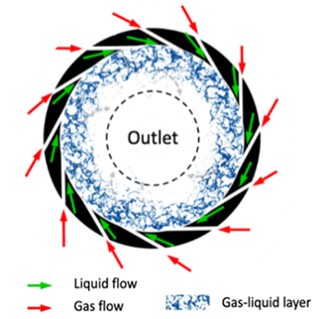
- Vortex unit acts as an absorber unit, intensifying the CO2 absorption in a static and compact unit. No mechanical rotation or packing is required, ensuring simple and safe operation.
- Vortex unit also acts as a desorber (stripper), intensifying the heat and mass transfer in the CO2 desorption and solvent regeneration process at reduced energy and size.
LIMITATIONS
- The high throughput in a compact unit limits the residence time. Therefore, the technology is best applicable in fast reaction systems, e.g., acidic gas scrubbing.
ENERGY
- Steam is utilized for CO2 desorption application as the gas phase, providing sufficient heat while acting as a carrier gas for the desorbed CO2.
- Electricity is used for compressing and pumping the gas and liquid flows to overcome the pressure drop in the vortex units.
CONSUMABLES
- Liquid solvent-based carbon capture process.
- Direct steam stripping for solvent regeneration.
- Cooling water is used after stripping to condense entrained water and solvent.
| Parameter | Value |
|---|---|
| Solvent make-up (kg/tCO2) | 0.75 |
| Cooling water (t/tCO2) | 74a |
| Heat (GJ/tCO2) | 2.7b |
| Electricity (MWh/tCO2) | 0.22c |
| *All results from CAPTIN project; a only 1.5% is lost and rest is recycled; b for 30 wt.% MEA; c includes CO2 compression supercritical state at 110 bar. | |
COSTS
CAPEX: 6.5 €/tCO2 *
Main CAPEX: gas blower, mechanical vapor recompression, main heat exchanger, and CO2 compressors.
(CAPEX may be underestimated due to basing the vortex reactor volume on laboratory-scale conditions.)
OPEX: 56 €/tCO2 *
Main OPEX: electricity and steam. Including CO2 compression to 110 bar.
CO2 capture cost: 62.5 €/tCO2*
Depends on lean solvent loading, capture efficiency, steam price, and waste heat utilization.
*CAPTIN project; NGCC plant; lifetime – 30 years; CO2 concentration – 4.6 vol.%; CO2 capture capacity – 1.5 MtCO2/yr; installation factor – 4; pressure – 1 bar; temperature – 25 °C; electricity price – 100 €/MWh; steam price – 25 €/t; includes CO2 compression to 110 bar; discount rate – 10%; WACC – 4.1%; 2020 euros.
CO2 avoidance cost: Not available.
ENVIRONMENTAL
CO2 footprint: Not available.
Spatial footprint: Not available.
Environmental issues: Solvent emissions, heat-stable salt disposal. Less solvent degradation compared to scrubbers is expected.
ENGINEERING
Maturity: Technology validated at lab-scale (TRL 4).
Time to market: 3-4 years.
Retrofittability: Feasible
Easily retrofittable with existing point sources or replacing existing scrubbers due to its compact and modular design.
Scalability: High
Scalability is also the main advantage of vortex compared to other technologies like microreactor, rotating packed bed, and so on.
Process type: Liquid solvent-based with chemical reactions.
Deployment model: Centralized or Decentralized.
Decentralized CO2 absorption at point sources with centralized desorption.
Technology flexibility: Hybridization with other capture technologies is feasible. Other technologies, such as membranes or PSA, can be used upstream to increase CO2 concentration.
TECHNOLOGY PROVIDERS
Laboratory for Chemical Technology (LCT)
Department of Materials, Textiles and Chemical Engineering
Technologiepark 125, 9052 Ghent, Belgium.
INNOVATIONS
- Superior mass and heat transfer efficiency lead to significant size reduction and heat transfer efficiency performance.
- 10x higher in mass transfer coefficient and specific interfacial area.
- 70% CAPEX reduction thanks to the compact design.
- Capture efficiency > 90% and regeneration efficiency > 70% achieved with 30 wt.% MEA.
- Static design for centrifugal force intensification without relying on the mechanism rotation.
- High degree of freedom to operate and easy scale-up.
BENCHMARK
Solvent-based scrubbing technology.
ALTERNATE PROCESSES
Carbon Clean’s CO2 capture technology uses rotating packed beds (RPB) to intensify gas-liquid contact, as opposed to swirling flow in gas-liquid vortex technology to create intense mixing and mass transfer without packing materials, offering simplicity and potentially lower pressure drop.
CONTACT INFO
For MAP-IT CCU
Mohammed Khan (mohammednazeer.khan@vito.be)
Miet Van Dael (miet.vandael@vito.be)
For Vortex technology
Yi Ouyang (Yi.Ouyang@ugent.be)
Geraldine Heydrinckx (Geraldine.Heynderickx@ugent.be)
Kevin M. Van Geem (Kevin.VanGeem@ugent.be)
ACKNOWLEDGEMENT
For MAP-IT CCU
This infosheet was prepared as part of the MAP-IT CCU project funded by VLAIO (grant no. HBC.2023.0544).
For Vortex technology
Catalisti cluster SBO project CAPTIN (HBC.2019.0109) and CAPTIN-2 (HBC.2021.0255) within the MOONSHOT Innovation Program.
REFERENCES
1. Ouyang Y, Nunez Manzano M, Wetzels R, et al. Liquid hydrodynamics in a gas-liquid vortex reactor. Chem Eng Sci. 2021;246:116970.
2. Ouyang Y, Manzano MN, Beirnaert K, Heynderickx GJ, Van Geem KM. Micromixing in a gas–liquid vortex reactor. AIChE J. 2021;67(7):e17264.
3. Ouyang Y, Nunez Manzano M, Chen S, et al. Chemisorption of CO2 in a gas–liquid vortex reactor: An interphase mass transfer efficiency assessment. AIChE J. 2022;68(5):e17608.
4. Chen S, Lang X, Kourou A, et al. Enhancing CO2 capture efficiency: Computational fluid dynamics investigation of gas-liquid vortex reactor configurations for process intensification. Chem Eng J. 2024;493:152535.
5. Dutta S, Roy S, Lang X, et al. Process Intensification of CO2 Desorption in a Gas-Liquid Vortex Reactor. Ind Eng Chem Res. 2024;63(24):10544-10553.