DESCRIPTION
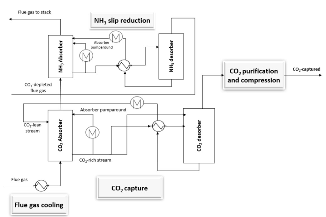
The chilled ammonia process (CAP) is a post-combustion carbon capture technology that uses an aqueous ammonia solution under chilled conditions, operating at temperatures between 0-10 °C.1 As shown in the schematic,2 the process begins with flue gas cooling in a direct contact cooler (DCC) to remove water vapor and lower the temperature, which is needed for the CO2 absorption process at lower temperatures (<20 °C).2 The cooled gas then enters the absorption column, where the cooled stream reacts chemically with the ammonia-based solution to form a CO2-rich solvent stream at the bottom of the absorber. This CO2-rich solvent is then heated in a desorber at elevated pressure, releasing CO2 as a high-pressure (up to 30 bar)2, relatively pure gas stream, ready for compression and storage, or utilization. Furthermore, residual ammonia in the treated flue gas is removed using cold water and acidic washes before the gas is released. The CAP offers several benefits over traditional amine-based solvents, including global availability, low cost, and chemical stability even in the presence of flue gas impurities like SOx and NOx. It also avoids the formation of toxic degradation products.
TECHNICAL ASPECTS (all % are volume-based)
Point sources: Fossil-fuel-based power plants, waste-to-energy & biomass power plants, cement plants, refineries, and petrochemical complexes.3
CO2 concentration range: 5% - 20%3–5
CO2 capture efficiency: ~90%6
CO2 purity: > 99.5%3
Min. feed gas pressure: 1.1 bar4
Max. feed gas temperature: 40 °C7
Typical scale: Medium to Large (> 100,000 tCO2/yr)3,6
Primary energy source: Electricity and Thermal (steam)
Impurity tolerance: Tolerant towards oxygen in flue gas and towards contaminants such as NOx and SOx.2,3
FUNCTION IN CCU VALUE CHAIN
- Capture CO2 from flue gases.
- The same ammonia stream can be used to remove SOx by scrubbing at the upstream of the CO2 absorber, avoiding the additional flue gas pretreatment step.4
- Elevated desorption pressure reduces post-capture compression power requirement.3
LIMITATIONS
- High energy consumption is primarily due to ammonia cooling and regenerating the absorbent solution.
- Equipment corrosion due to the nature of ammonia.
- Water usage, especially in the absorption and washing stages.
ENERGY
- Heat (steam at 145 °C)4 used in the desorber for regeneration of the CO2-rich solvent stream.
- Electricity is used for the refrigeration of ammonia and the pumping of the CO2-rich solvent.
CONSUMABLES
- Ammonia is used to capture CO2 from flue gas.
- Cooling water is used in the downstream of the desorber column to condense entrained water and solvent vapors.
| Parameter | Value |
|---|---|
| Heat (GJ/tCO2) | 2.34 - 2.63 |
| Electricity (kWh/tCO2) | 87 - 944 |
| Ammonia make-up (kg/tCO2) | 2 - 34 |
| Cooling water make-up (t/tCO2) | 2.08 |
| Process water make-up (kg/tCO2) | 9 - 144 |
| Sulfuric acid (kg/tCO2) a | 0.6 - 1.04 |
|
4,8 Cement plant; clinker capacity: 1 Mt/yr; specific CO2 emission – 0.85 tCO2/tclk; NH3 concentration – 9 wt.%; CO2 stream at 25 bar from desorber; includes CO2 compression of only one stage. a Sulfuric acid is used in ammonia recovery. |
|
COSTS
CAPEX: 19 €/tCO2 8; 33 €/tCO2 9
Main CAPEX: Absorbers, desorbers, and refrigeration unit.
OPEX: 34 €/tCO2 8; 26 €/tCO2 9
Main OPEX: steam, electricity
CO2 capture cost: 53 €/tCO2 8; 59 €/tCO2 9
CO2 avoidance cost: 66 €/tCO2 avoided 8
68 €/tCO2 avoided 9
8 Cement plant; clinker capacity: 1 Mt/yr; lifetime - 25 years; heat (NG) – 6 €/GJ; electricity – 58.1 €/MWh; cooling water – 0.39 €/m3; process water – 6.65 €/m3; ammonia – 406 €/ton; discount rate – 8%; 2014 euros; specific CO2 emission – 0.85 tCO2/tclk; NH3 concentration – 9 wt.%; includes CO2 compression and purification.
9 Steam power plant; CO2 capacity – 0.98 MtCO2/yr; lifetime - 30 years; heat (NG) – 6 €/GJ; electricity – 77.5 €/MWh; ammonia – 672 €/t; discount rate – 8%; 2022 euros; NH3 concentration – 7 wt.%; includes CO2 compression and purification.
ENVIRONMENTAL
CO2 footprint: 134 kgCO2e/tCO2 9
(Calculated: steam power plant stack emissions = 892 kgCO2/MWh; CAP GWP (emissions) = 119.4 kgCO2eq/MWh)
Spatial footprint: 4.56 m2 per tonne per day of CO2 capture 7
(Alstom’s CAP pilot plant in Technology Center Mongstad, Norway, designed in 2008)
Environmental issues: Ammonia slip, water usage, fine aerosols.7
ENGINEERING
Maturity: Operational (TRL 7 - 8)4
Retrofittability: Moderately4
It can be installed in existing facilities, such as power plants and cement production sites, but requires sufficient space for additional equipment like absorbers, desorbers, and refrigeration units.
Scalability: High4
Well-suited for capturing large amounts of CO2 from large point sources.
Process type: Liquid solvent-based with chemical reactions.
Deployment model: Centralized or Decentralized.
Decentralized CO2 absorption at point sources with centralized desorption.
Technology flexibility: Hybridization with other capture technologies is feasible. Other technologies, such as membranes, can be used upstream to increase CO2 concentration.
TECHNOLOGY PROVIDERS
- Chilled Ammonia Process by Baker Hughes, United States
- Chilled Ammonia Process by Alstom, France
- Chilled Ammonia Process by General Electric, United States10
BENCHMARK
MEA-based primary amine scrubbing technology serves as the benchmark for all the CO2 capture technology due to its wider applications and high commercial readiness.
CONTACT INFO
Mohammed Nazeer Khan (mohammednazeer.khan@vito.be)
Miet Van Dael (miet.vandael@vito.be)
ACKNOWLEDGEMENT
This infosheet was prepared as part of the MAP-IT CCU project funded by VLAIO (grant no. HBC.2023.0544).
REFERENCES
1. Darde V, Thomsen K, van Well WJM, Stenby EH. Chilled ammonia process for CO2 capture. Int J Greenh Gas Control. 2010;4(2):131-136.
2. Amara S. CO2 Capture in Industry Using Chilled Ammonia Process.; 2020.
3. Barlow H, Shahi SSM. State of the Art: CCS Technologies 2024.; 2024.
4. Voldsund M, Gardarsdottir SO, De Lena E, et al. Comparison of Technologies for CO2 Capture from Cement Production—Part 1: Technical Evaluation. Energies. 2019;12(3):559.
5. Kozak F, Petig A, Morris E, Rhudy R, Thimsen D. Chilled ammonia process for CO2 capture. Energy Procedia. 2009;1(1):1419-1426.
6. Telikapalli V, Kozak F, Leandri JF, et al. CCS with the Alstom chilled ammonia process development program–Field pilot results. Energy Procedia. 2011;4:273-281.
7. Subramani A. Techno-Economic Assessment of a Post-Combustion CO2 Capture Unit in SCA Östrand Pulp Mill. KTH Royal Institute of Technology; 2022.
8. Gardarsdottir SO, De Lena E, Romano M, et al. Comparison of Technologies for CO2 Capture from Cement Production—Part 2: Cost Analysis. Energies. 2019;12(3):542.
9. Slavu N, Badea A, Dinca C. Technical and Economical Assessment of CO2 Capture-Based Ammonia Aqueous. Processes. 2022;10(5):859.
10. Augustsson O, Baburao B, Dube S, et al. Chilled Ammonia Process Scale-up and Lessons Learned. Energy Procedia. 2017;114:5593-5615.