DESCRIPTION
TECHNICAL ASPECTS (all % are volume-based)
Point sources: Cement plants, waste to energy, power plants, iron and steel production, chemical plants.2,3
CO2 concentration range: 15 – 35%4 (typical)
CO2 capture efficiency: >95%5
CO2 purity: 95%5
Min. feed gas pressure: ~1 bar6
Max. feed gas temperature: 650 °C5
Typical scale: Large (> 100,000 tCO2/yr)5
Primary energy source: Thermal (waste heat)
Impurity tolerance: SO2 is captured due to the affinity of calcium oxide (CaO) to form calcium sulfate (CaSO4).6
FUNCTION IN CCU VALUE CHAIN
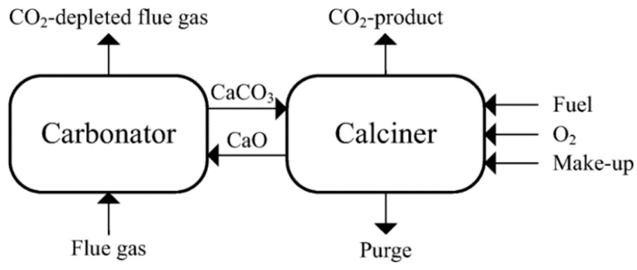
- Capture CO2 from flue gases.
- Removal of impurities such as SO2, avoiding the use of an additional pre-treatment step.
- Can accommodate high-temperature flue gases, avoiding the use of an upstream gas cooler.
LIMITATIONS
- High energy demand for the calcination step.
- Sorbent degradation over multiple carbonation-calcination cycles.
- Performance is highly dependent on the CO2 concentration in the flue gas.
ENERGY
- Thermal energy is the primary source for the calcination process.
- Electricity is only used for auxiliary systems.
CONSUMABLES
- Primary calcium oxide (CaO) is used as a sorbent material.
- Cooling water is used in the cooling cycle.
- Oxygen produced in an air separation unit is used in the calciner.
| Parameter | Value |
|---|---|
| CaO sorbent makeup (t/tCO2) | 0.76 5,7 |
| Heat (GJ/t-CO2) | 2.7 – 4.7 5,7 a |
| Electricity consumption (kWh/tCO2) | 261 – 313 5,7 a |
| Electricity generation (kWh/tCO2) b | 211 – 400 5,7 a |
| Cooling water makeup (t/tCO2) | 1.9 – 2.3 7,8 a |
| Oxygen use (t/tCO2) | 0.38 7 |
|
a Values for CaL integrated with a cement plant. Lower range values are for the CaL integrated system, and higher range for the CaL tail-end system with 50% integration. Includes energy for CO2 compression and purification. b Pure hot CO2 stream is re-used to generate steam to produce electricity at an efficiency of 45.9%. When integrated with a cement plant, there is net power generation. |
|
COSTS
CAPEX: 17 - 22 €/tCO2 8
Main CAPEX: air separation unit, CO2 compression and purification unit, carbonator, and calciner.
OPEX: 17 – 21 €/tCO2 8
Main OPEX: fuel costs, electricity, labor, and maintenance.
CO2 capture cost: 34 – 43 €/tCO2 8
CO2 avoidance cost: 52 – 59 €/tCO2 avoided 8
8 Cement plant; clinker capacity: 1 Mt/yr; lifetime - 25 years; heat (coal) – 3 €/GJ; electricity – 58.1 €/MWh; cooling water – 0.39 €/m3; process water – 6.65 €/m3; discount rate – 8%; 2014 euros; specific CO2 emission – 0.85 -CO2/tclk; includes CO2 compression and purification; lower range values are for CaL integrated system, and higher range for CaL tail-end system with 50% integration.
ENVIRONMENTAL
CO2 footprint: 185 kgCO2e/tCO2 9
(calculated; coal power plant stack emissions = 0.863 kgCO2/kWh; captured CO2 = 0.744 kgCO2/kWh; CaL emissions = 0.138 kgCO2/kWh)
Spatial footprint: 3000 m2 for 154 ktCO2/yr 10
(Dimensions H/D in meters – carbonator 11.04/2.72 and calciner 11.19/2.13; excluding secondary power generation unit)
Environmental issues: Sorbent degradation, waste generation, and raw material extraction.
ENGINEERING
Maturity: Pilot plant (TRL 6-7)3,11
A pilot plant is already operational in La Pereda, Spain.
Retrofittability: Moderate12
Challenges when integrating with existing power plants and industrial facilities, such as cement and steel plants. The spatial footprint can be optimized by integrating the new equipment with the existing infrastructure.
Scalability: High
Applications range from small pilot plants to large industrial facilities. Due to easy integration with an existing facility, scaling up without the need for entirely new infrastructure is possible.
Process type: Solid circulating sorbent-based with chemical reactions.
Deployment model: Centralized only.
Handling of solid sorbent (CaO and CaCO3) in large volumes can be complex and costly. Maintaining high temperatures is challenging and less efficient.
Technology flexibility: Hybridization with other capture technologies is feasible. Other technologies can be used to increase the CO2 concentration. Capture costs decrease with increasing CO2 concentration.
TECHNOLOGY PROVIDERS
INNOVATIONS
- CaLby2030 Project: This project is funded by the Horizon Europe framework and aims to achieve commercial deployment of calcium looping technology by 2030. The project focuses on using Circulating Fluidised Bed (CFB) reactors to demonstrate CO2 capture rates greater than 99% in three hard-to-abate industrial sectors: cement, steel, and waste-to-energy.
- Magnesium Looping (MgL)13: CO2 is captured through the carbonation of MgO, forming magnesium carbonate (MgCO3), which is subsequently regenerated to release CO2.
- Ca-Cu Looping (CaCuL)14: This process combines calcium and copper looping to capture CO2 and produce hydrogen-rich gases. It involves a series of reactions, including the reduction of CuO to Cu and the carbonation of CaO.
CONTACT INFO
Mohammed Khan (mohammednazeer.khan@vito.be)
Miet Van Dael (miet.vandael@vito.be)
ACKNOWLEDGEMENT
This infosheet was prepared as part of the MAP-IT CCU project funded by VLAIO (grant no. HBC.2023.0544).
REFERENCES
1. Michalski S, Hanak DP, Manovic V. Advanced power cycles for coal-fired power plants based on calcium looping combustion: A techno-economic feasibility assessment. Appl Energy. 2020;269(April 2019):114954.
2. Criado YA, Arias B, Abanades JC. Calcium looping CO2 capture system for back-up power plants. Energy Environ Sci. 2017;10(9):1994-2004.
3. Barlow H, Shahi SSM. State of the Art: CCS Technologies 2024.; 2024.
4. Maddox RN, Morgan DJ. Gas Conditioning and Processing. 4th ed. John M. Campbell and Company; 2006. Accessed April 11, 2022. https://books.google.ca/books/about/Gas_Conditioning_and_Processing.html?id=i6VLAAAACAAJ&redir_esc=y
5. De Lena E, Spinelli M, Gatti M, et al. Techno-economic analysis of calcium looping processes for low CO2 emission cement plants. Int J Greenh Gas Control. 2019;82(January):244-260.
6. Schakel W, Hung CR, Tokheim LA, Strømman AH, Worrell E, Ramírez A. Impact of fuel selection on the environmental performance of post-combustion calcium looping applied to a cement plant. Appl Energy. 2018;210:75-87.
7. Voldsund M, Gardarsdottir SO, De Lena E, et al. Comparison of Technologies for CO2 Capture from Cement Production—Part 1: Technical Evaluation. Energies. 2019;12(3):559.
8. Gardarsdottir SO, De Lena E, Romano M, et al. Comparison of Technologies for CO2 Capture from Cement Production—Part 2: Cost Analysis. Energies. 2019;12(3):542.
9. Clarens F, Espí JJ, Giraldi MR, Rovira M, Vega LF. Life cycle assessment of CaO looping versus amine-based absorption for capturing CO2 in a subcritical coal power plant. Int J Greenh Gas Control. 2016;46:18-27.
10. Vora MJ. Calcium Oxide Based Carbon Capture in District Energy Systems. KTH Royal Institute of Technology; 2022. https://www.diva-portal.org/smash/get/diva2:1693494/FULLTEXT01.pdf
11. Arias B, Alvarez Criado Y, Méndez A, Marqués P, Finca I, Abanades JC. Pilot Testing of Calcium Looping at TRL7 with CO2 Capture Efficiencies toward 99%. Energy and Fuels. 2024;38(15):14757-14764.
12. Yin J, Li C, Su S, Yu XX, Paicu G. Retrofitting Calcium Carbonate Looping to an Existing Cement Plant for CO2 Capture: A Techno-Economic Feasibility Study.; 2020.
13. Perejón A, Arcenegui-Troya J, Sánchez-Jiménez PE, Diánez MJ, Pérez-Maqueda LA. Magnesium calcites for CO2 capture and thermochemical energy storage using the calcium-looping process. Environ Res. 2024;246:118119.
14. Díaz M, Alonso M, Grasa G, Fernández JR. The Ca-Cu looping process using natural CO2 sorbents in a packed bed: Operation strategies to accommodate activity decay. Chem Eng Sci. 2023;273:118659.