Synonyms, abbreviations and/or process names
- Recuperative catalytic afterburning
Removed components
- VOC’s, odour
- Carbon monoxide
- Halogenated compounds (specific catalysts required)
- CO
- (Fine organic particles)
Diagram
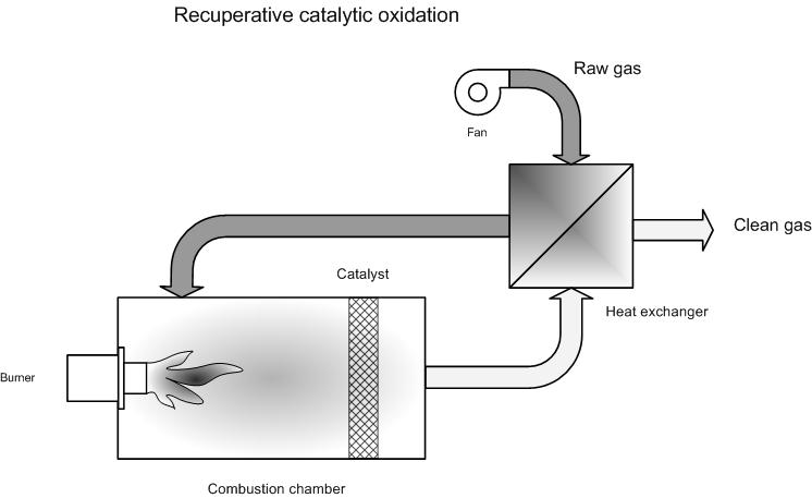
Process description
The process involves a recuperative heat exchanger( see recuperative thermal oxidation) , whereby the afterburning section is catalytic (see catalytic oxidation).
The yield for heat recuperation can be as high as 76 %, as in recuperation with non-catalytic afterburning. In recuperative catalytic afterburing, autothermic combustion is possible from 2 - 4 g/m³ of solvent [5]. According to BAT [7] the concentration limit is 3 – 6 g/m³ for a thermal yield of 50 – 70 %. According to BAT [8] the autothermal point lies between 4 – 8 g/m³.
Variants
See regenerative catalytic oxidation
Efficiency
See regenerative catalytic oxidation
Boundary conditions
The boundary conditions for catalytic afterburning remain valid (see catalytic oxidation).
Particular attention must be paid to polluted gases (fats, dust…). These may foul the heat exchanger and cause blockages. Fouling will initially lead to a fall in yield. Dust concentrations should be less than 3 mg/m³. In specific applications for burning organic matter, this can higher [5].
For corrosive gases, one must be wary of the selected material in order to limit/avoid corrosion.
In the interest of safety, the hydrocarbon concentration in the flue gas mix must be kept below 25% of the lowest explosion limit (LEL).
Auxiliary materials
The need for additional fuel falls considerably compared to the situation without heat recuperation (see catalytic oxidation)
Environmental aspects
Energy use
The energy use is lower than for catalytic afterburning without heat recuperation. Use is determined by the flow rate and the hydrocarbon concentration in flue gases. Autothermicity is realised from 3 -6 g/m³ VOC.
Cost aspects
Investment
- 10 000 -50 000 EUR for 1 000 Nm³/h [7]
Examples
Case study: small afterburner [6]
Flow rate: 4 500 Nm³/h
Solvent concentration: 0 - 2.8 g/Nm³
Yield heat exchanger: 65%
- Investment of 131 000 EUR
- Fuel use: 188 - 320 kW
Yield heat exchanger: 80 %
- Investment of 159 000 EUR
- Fuel use: 17 - 182 kW
Baking ovens case study [6]
- Flow rate: 4 400 Nm³/h
- Investment costs: 110 000 EUR
Printing lines case study [6]
- Flow rate: 2 000 Nm³/h
- Investment costs: 100 000 EUR
Ethylene oxide case study [6]
- Flow rate: 4 000 Nm³/h
- Investment costs: 150 000 EUR
- High investment costs for safety precautions for ethylene oxide
Baking ovens case study 1 [6]
- Flow rate: 14 000 Nm³/h
- Investment costs: 230 000 EUR
Metal-processing industry case study [8]
- Flow rate: 20 000 Nm³/h
- Investment costs: 260 000 EUR
Advantages and disadvantages
Advantages
- See technique sheet 33
- Lower fuel costs
Disadvantages
- See technique sheet 33
- The heat exchanger may cause fouling at high dust-contents
Applications
- Graphics sector
- Baking ovens
- Spraying booths
References
- BREF: "Common waste water and waste gas treatment /management systems in the chemical sector" EIPPC, February 2002
- Factsheets on Air-emission reduction techniques, www.infomil.nl, Infomil
- EPA Air Pollution Technical factsheet: Catalytic incinerator
- EPA Air Pollution Technical factsheet: incinerator: recuperative type
- VDI 2587 part 1: Emission control: heatset web offset presses, November 2001
- Supplier information
- A. Jacobs, B. Gielen, I. Van Tomme, Ch. De Roock and R. Dijkmans., Best Available Techniques for the wood processing industry, October 2003
- L. Goovaerts, M. De Bonte, P. Vercaemst and R. Dijkmans., Best Available Techniques for the metal processing industry, December 2003
- A. Derden, J. Schrijvers, M. Suijkerbuijk, A. Van de Meulebroecke1, P. Vercaemst and R. Dijkmans., Best Available Techniques for the slaughterhouse sector, June 2003