Synonyms, abbreviations and/or process names
- Solvent recuperation
- Air separation with membranes
- Vaconocore
Removed components
Solvents:
- alkanes
- olefins
- aromates
- alcohols
- ethers
- esters
- ketones
Chlorinated solvents:
- dichloroethane
- trichloroethane
- vinyl chloride
- monochlorobenzene
N2 removal from air with simultaneous production of O2-enriched air
H2 from refinery gas
Moisture from:
- compressed air
- solvents
Diagram
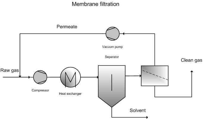
Process description
Membrane filtration exploits the fact that solvents migrate easier through a membrane than oxygen, nitrogen and CO2 (10 – 100 times better [3], 2 – 400 times better [5]).
Air laden with solvents is compressed and passed via a membrane. The membrane stops the air and allows solvents to pass through. The to-be-cleaned air is subject to overpressure (0.1 - 1 Mpa). The other side of the membrane is kept under underpressure (approximately 0.2 – 150 kPa) via a vacuum pump. Due to the difference in partial pressure, the solvents migrate through the membrane.
As a result, one gets a solvent-poor and a solvent-rich gas stream. The solvent-poor gas stream must be further treated via another purification technology like adsorption, photo oxidation, afterburning, biological purification…
The solvents are recuperated from the solvent-rich stream by performing condensation. This is possible, as the figure shows, after mixing with the original stream. Recuperation can also take place before mixing with the entry stream. There are a few viable variants.
For high solvent concentrations, prior condensation will take place in the heat exchanger after the compression phase, where the solvents will be separated. This is useful for reducing the load on the membrane.
The installation is dimensioned on the basis of flow rate, solvent concentration, solvent type, membrane type (surface load), required recuperation grade, required solvent concentration…
Because solvent concentration varies in the concentration build-up of solvents, from the lowest explosion limit to the highest explosion limit, there is a risk of explosion in the membrane module. This must be considered during the design phase.
Variants
Membrane installations are also available for the production of nitrogen gas, nitrogen-enriched air (82% instead of 78% for NOx reduction in engines) and oxygen-enriched air (31% instead of 21% for clinical purposes or combustion purposes).
The membrane configuration depends on the supplier: This varies from smooth membranes to hollow fibre membranes. There is also a choice between organic and inorganic membranes. Inorganic membranes are more resistant against temperature and fouling. These membranes are primarily used in gas purification of nuclear fuels and for the separation of mixes of hydrogen/nitrogen, hydrogen/methane, helium/methane, oxygen/nitrogen, CO2/CH4, hydrocarbons from air…[5]. Inorganic membranes are more resistant against extreme gas conditions (e.g. temperature-related).
Efficiency
- Dichloromethane [1]:
- Inlet concentration: 10 – 30 %
- End concentration: 150 mg/Nm³
- 1,2 Dichloromethane [1]:
- Inlet concentration: 80 g/Nm³
- End concentration: 320 mg/Nm³
- Hydrocarbons:
- Butane [5]:
- Inlet concentration: 300 ppm
- End concentration: 70 ppm
Boundary conditions
- Ambient temperature (determined by membrane)
- Pressure:
- 3.5 bara [2] (bara = absolute pressure)
- 5 barg in process [1] (barg = overpressure compared to ambient pressure or = bara - 1)
- Up to 100 bara in inorganic membranes [5]
- Solvent concentration minimum a few g/Nm³
- Dust: Very low concentration needed to protect the membrane
- Relatively low gas volumes: Capacities from 2 100 – 3 000 Nm³/h have been recorded [3]
- Solvent concentrations up to 90% can be realised [3]
- Solvent concentrations: Typically between1 -10% [6]
Auxiliary materials
The membrane will need to be replaced periodically. The life-span guarantee for membranes is 5 years [4].
Environmental aspects
The technique is used for recuperation, which means the concentrated stream is reused.
Residual emissions normally need to be further treated. In particular cases, the solvent concentration can be immediately reduced to beneath the limit value by using membrane separation.
Energy use
Energy use consists of ventilator costs and costs for the vacuum pump. The pressure drop over the membrane is 0.1 -1 MPa. The total energy use amounts to between 250 kWh/1 000 Nm³/h [2] and 300 kWh per 1 000 Nm³/h [4] (incl. ventilator)
Cost aspects
Investment
Operating costs
- Personnel: 4 days per year
- Energy costs:
- Cost-saving possible via recuperated solvents
- Total operating costs typically less than 50 EUR per 1 000 Nm³
- Cost-determining parameters:
- Flow rate;
- Technical life-span of membrane;
- Required recovery;
- Required end concentration;
- Type of components
If a product with a high unit price is recuperated, money-return periods of 4 months to 1 year have been stated. This is only possible with favourable process conditions. In less favourable cases the technique will not pay for itself, but will be classed as a saving compared to other air purification techniques.
Production of nitrogen gas, prices 1995 [5]
- Capacity: 3 ton/day
- Purity: 95 % N2
- Investment costs: 90 000 USD
- Operating cost:
- Membrane replacement: 16 USD/day
- Energy: 35 USD/day
- Amortisation: 46 USD/day
- Other: 9 USD/day
- Total cost per day: 106 USD/day
- Costs for nitrogen: 35 USD/ton
Production of oxygen-enriched air, prices 1995 [5]
- Capacity: 10 ton/day oxygen/day
- Purity: 35 % O2
- Investment costs: 288 000 USD
- Operating cost:
- Membrane replacement: 38 USD/day
- Energy: 86 USD/day
- Amortisation: 138 USD/day
- Other: 18 USD/day
- Total cost per day: 280 USD/day
- Costs for nitrogen: 28 USD/ton
3-phase system to recuperate freon CFK-113 [5]
- Capacity: 850 Nm³/h
- Ingoing concentration: 3% in air
- End concentration: 0.075 %
- End product: Clear liquid from CFK-113
- Investment costs: 650 000 USD
- Energy costs: 63 500 USD/year
- Operating cost incl. amortisation: 44 USD per 1 000 Nm³ feed
- Cost per kg product: 0.46 USD/kg
Advantages and disadvantages
Advantages
- Re-use of raw materials
- Easy to use
- No residue produced
Disadvantages
- Membrane filtration is only a concentration technique and must be followed-up by a second phase (e.g. condensation or cryocondensation)
- Risk of explosion
Applications
- Nitrogen gas production (97 – 98% purity) and production of air enriched with oxygen.
- Recuperation of benzene and solvent vapours from storage tanks (occurring during filling).
- Recuperation of 1.2-dichloroethane in the production of monovinylchloride.
- Recuperation of monovinylchloride in PVC production.
- Recuperation of dichloromethane from concentrated flue gases from an industry that uses this substance as a solvent.
- Recuperation of olefin monomers from flue gases from degassing polyolefins in polymer production.
- Hydrogen recuperation from refinery gas.
- Recuperation of organic substances from refinery flue gases.
- Continuous removal of the product formed in a chemical reactor when maintaining ideal reaction conditions and encouraging effective reactions.
- Helium recuperation from hydrocarbons or nitrogen gas.
- Hydrogen separation from synthesis gas for correcting the CO/H2 ratio, from nitrogen gas in ammonia production and from hydrocarbons for hydrogen recuperation.
- CO2 separation from natural gas and biogas, to increase gas value.
- Drying of air and other gases.
References
- Supplier information
- Factsheets on Air-emission reduction techniques, www.infomil.nl, Infomil
- BREF: "Common waste water and waste gas treatment /management systems in the chemical sector" EIPPC, February 2002
- Environmental Technology Monographs Handbook, Handbook on Gaseous Waste, Envi Tech Consult, The Netherlands, 1993
- R.D. Noble , S.A. Stern: Membrane Separation Technology: principles and applications, Elsevier Science 1995
- Solvent capture for recovery and re-use from solvent laden gas streams, Environmental Technology Best Practice programme, guide GG 12