Synonyms, abbreviations and/or process names
- Lime injection
- Fixed-bed lime adsorption
- Cascade adsorption
Removed components
Acidic components:
- SOx
- HCl
- HF
- Other
Diagram
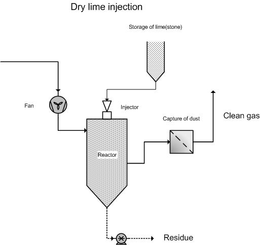
Process description
Lime injection is a technique which involves acidic components in smoke and flue gases, such as HC1, HF and particularly SO2, being removed via chemisorption.
During dry flue gas cleaning, dry lime or limestone is sprayed into the flue gas. The reaction between the dry lime or limestone and the acidic components in the flue gas takes place in a reactor, and partly in a later employed dust separation phase, once the pollutants have been absorbed by the lime via chemisorption. The reactor is needed to guarantee a long enough reaction time, of a few seconds, between the chemicals and the pollutants in the flue gas stream. Lime injection takes place in the reactor. However, it is also possible to inject lime into the flue gas prior to the reactor.
If a fabric filter is used to remove the reaction product, there will be better contact between the lime and gaseous pollutants than if an E filter is used. When selecting the size of the reactor, and when determining the amount of chemicals that will be required, the choice of emission-reducing technique (for the removal of dust) is of key importance. The reaction takes place once the gaseous pollutants have been adsorbed by the lime. Due to the low contact surface area, the amount of chemicals required is much greater than for a semi-dry cleaning method. Together with the separation of the dry reaction products and of the excess chemicals, it is also possible to separate dust-like particles. The used chemicals are partly recirculated along with the separated pollutant. Even so, chemical use and quantity of collected dust in dry cleaning is considerably higher than in semi-dry cleaning.
Variants
Cascade or bed adsorption
In this case, the adsorbents are not injected into the gas stream, but the gas stream is passed through a fixed adsorption bed. The reaction between the adsorption medium, most commonly calcium carbonate, and the flue gas pollutants takes place in an area where the adsorbents sink under the force of gravity, and where flue gases are passed through in a counter-flow or cross-flow direction. In order to create sufficient reaction time and contact surface area, obstacles have been placed in these areas which help to slow the falling speed of adsorbents and help to ensure efficient circulation and dispersion of flue gases in the installation. The reacted calcium carbonate is collected at the bottom of the installation.
The adsorbents used are in granule form and must satisfy certain specifications in terms of size, composition and porosity in order to realise the maximum cleaning yield.
Because adsorption of SO2, HCl and HF primarily takes place on the outside of the calcium carbonate grains, the adsorption yield of the grains is relatively low. In order to increase this yield, a peeling technique can be implemented. This involves the softer outer-layer, which is made up of calcium fluoride, calcium sulphite and calcium chloride, being removed mechanically. The remaining grain can once again be used as adsorbent if it fulfils size requirements.
Sorbalite
This technique involves injecting a mixture of lime and activated carbon. The advantage of this approach is that it not only removes acidic components, but the activated carbon ensures that PCDF’s and PCDD’s are, for the most part, also adsorbed. This technology also leads to large quantities of heavy polluted residue.
Efficiency
The removal efficiency is determined by various factors, such as:
- Temperature
- The molar ratio between polluted component and sorbents
- The way in which sorbents disperse
- The technique used for dust collection
Existing values are [2].
SOx: 40 – 80 %
HCl: 50 – 75 %
HF: 10 – 40 %
Boundary conditions
In most cases, it is necessary for flue gases to be conditioned beforehand, using water for example. This helps to keep the temperature, as well as the humidity in flue gases, within established boundaries.
- Flow rate: 10 000 – 300 000 Nm3/h
- SOx: Broad range
- HCl: Broad range
- HF: Broad range
Auxiliary materials
- Sorbents at an excess of 2 to 4 times the stoichiometric quantity, depending on desired residue emission
- Possibly other substances such as activated carbon, Sorbalite (activated carbon + lime)
- Sorbents like slaked lime, unslaked lime, limestone or Wülfragan (modified calcium carbonate) can be used, depending on the application and the system.
Environmental aspects
Residue collected in the dust separator or at the bottom of the fixed bed.
Energy use
Energy use is determined by the dust separation system.
Cost aspects
- Investment
- For lime injection systems, the cost aspects are determined by the type of dust-removal system.
- Case study:
- For the removal of acidic components HF, SOx from the flue gases from a brick oven, via cascade or bed adsorption, for a flue gas flow rate of 30 000 Nm³/h, the investment amounts to ca. 174 000 EUR for a cascade installation with normal CaCO3, 620 000 EUR for a cascade installation with Wülfragran, and 843 000 EUR for an injection system [7].
- Operating costs
- Personnel costs: ca. 2 500 EUR per year (2 hours per week)
- Auxiliary and residual materials: [6, 7]
- Cost aspects CaCO3: ca. 60 EUR/ton
- Cost aspects Wülfragan: ca. 100 EUR/ton
For flue gases originating from a brick oven with a flow rate of 50 000 Nm³/h and the following configuration:
|
Acidic component |
Concentration (mg/Nm3) |
Boundary limit 2010 (mg/Nm3) |
Removal Yields (%) Wülfragan |
|
SOx |
1 500 |
500 |
43 |
|
SO3 |
150 |
|
80 |
|
HF |
76 |
5 |
99 |
|
HCl |
7 |
30 |
50 |
For a stoichiometric excess of 2.5, the use of Wülfragan is 223 kg/h or 5 352 kg/day (24-hour operation). On an annual basis (200 working days) this means 1 070 tonnes per year, which comes down to 21 tonnes per year per 1 000 Nm3/h or 2 100 EUR per year per 1 000 Nm3/h.
The disposal costs for chemical waste amount to 150 – 250 EUR/ton.
Advantages and disadvantages
Advantages
- Low extra investment costs when a dust-removal installation is present;
- High yields can be realised with an effective reactor design;
- No waste water;
Disadvantages
- Large excess of sorbents required;
- Large quantities of residue to be disposed of;
- Residue with an excess of sorbents;
- Lime dosage may encounter problems due to blockages
Applications
As a flue gas purification technique for combustion processes in:
- Waste combustion installations;
- Glass industry
- Ceramics industry
References
- Factsheets on Air-emission reduction techniques, www.infomil.nl, Infomil
- Common waste water and waste gas treatment and management systems in the chemical sector. BREF document, European IPPC Bureau, http://eippcb.jrc.es
- Elslander H., De Fré R., Geuzens P., Wevers M. (1993). Comparative evaluation of possible gas purification systems for the combustion of household waste. In: Energie & Milieu, 9
- Vanderreydt I. (2001). Inventory of the waste incineration sector in Flanders. Vito, 2001/MIM/R/030
- Work-book on environmental measures: Metal and electro-technical industry (1998 ), VNG publishers
- Supplier information
- Huybrechts D., Vercaemst P. and Dijkmans R., Best Available Techniques for the clay-processing industry, 1999
- L. Goovaerts, W. Luyckx, P. Vercaemst, G. De Meyer and Dijkmans, Best Available Technique for combustion plants and stationary engines, 2002
- VDI 3928, Abgasreinigung durch Chemisorption