Synonyms, abbreviations and/or process names
- SCR
Removed components
- NOx
Diagram
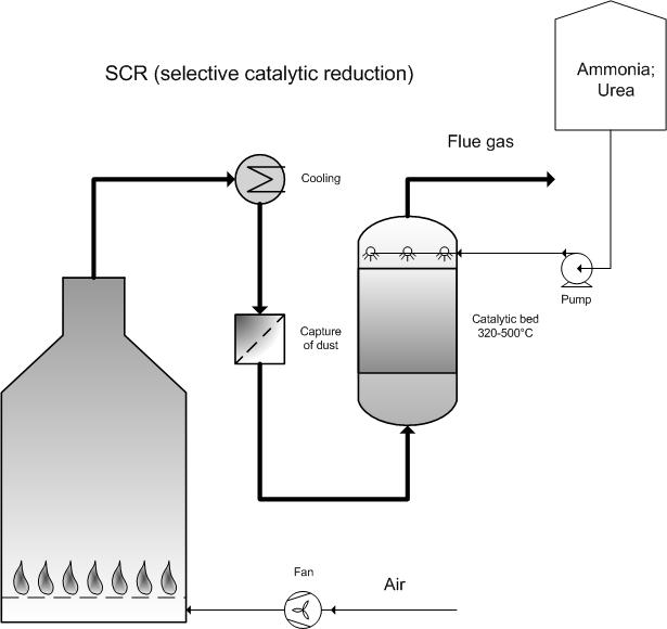
Process description
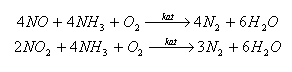
During the SCR process (Selective Catalytic Reduction) NOx is reduced to N2 and H2O by adding NH3 or ureum in the presence of a catalyst, as in the following reaction diagram:
The optimum process temperature lies between 320 – 500 °C depending on the catalyst.
Oxides of vanadium, wolfram, molybdenum or other metals are often used as a catalyst, with titanium oxide as the carrying material. An optimum mix in the catalyst bed and a molar ratio of 1:1 for NH3/NOx are the most important process parameters for ensuring the most comprehensive reaction and thus avoiding unwanted ammonia emissions (NH3 slip).
The lifespan of the catalyst is primarily determined by the erosion caused by the flue gas, deactivation caused by poisoning (NH4HSO4) and the build-up and fouling by the catalyst.
Special attention must be paid to start-up and shut-down of the installation. It is important to stop NH3 injection when the temperature drops below a particular level, in order to prevent ammonium water sulphate building-up on the catalyst.
Variants
The SCR installation can be placed immediately after the boiler (high-dust switching).
A second possibility is to later employ a SCR unit after the fabric filters or scrubbers (low-dust switching). This requires the flue gas to be heated to reaction level.
Efficiency
NOx: 90-94%
Residual emissions: Possible aerosol-forming from ammonium chloride and ammonium sulphate.
Boundary conditions
- Flow rate: 1 000 000 Nm³/h
- Temperature: 200 - 500 °C depending on the catalyst
- NOx: In the range g/Nm³
- NH3/NOx ration: < 1:1
In the presence of SO3 the ammonium is collected via the forming of ammonium sulphate. The ammonium sulphate can block the catalyst and is emitted as a difficult-to-separate aerosol.
Auxiliary materials
Reductants: 25% solution of ammonium or ureum
Steam: To aerate the reductant before it is injected.
Catalyst: V2O5 (vanadium pentoxide) and/or TiO2 (titanium dioxide), etc.
Environmental aspects
- Possible NH3 emissions due to the process not being completed effectively (NH3 slip).
- Used catalyst
- Laughing gas (N2O) can be produced as a by-product.
- In "high-dust" switching, the flue gases are laden with NH3;
Energy use
Energy use for heating flue gases in "low-dust configuration.
Cost aspects
Investment
- 7 500 -32 000 EUR for 1 000 Nm³/h (strongly determined by application) [1,2]
- For a household-waste incineration plant with a capacity of ca. 80 000 ton per year and a flue gas flow rate of 60 000 Nm3/h, the investment costs amount to ca. 5 000 000 EUR [6].
Operating costs
- Personnel costs: ca. 20 000 EUR per year
- Auxiliary and residual materials: Up to 370 kg NH3 solution per ton NOx removed
- Cost aspects NH3: 150 EUR/ton
For flue gases from a household-waste incineration plant, the average gas composition for NOx is 335 mg/Nm3 (VITO measurement 1999). This is equivalent to an average emission of 2 141 g/ton waste. For an installation of 18 ton/h, this corresponds to 38 kg/h NH3. In order to reduce NOx emission by 50% the use of NH3 amounts to an average of 19 kg/h or 465 kg/day. On an annual basis, this means ca. 17 ton per year per 1 000 Nm3/h or 2 550 EUR per year per 1 000 Nm3/h.
Advantages and disadvantages
Advantages
- Higher NOx reduction yield compared to SNCR
- Relatively simple installation
Disadvantages
- For relatively high SO3 contents, the process must be performed at a relatively high temperature in order to avoid condensation.
- In "high-dust" switching, the flue gases are laden with NH3.
- Cost aspects of catalyst
- Possibility of blocking and poisoning of the catalyst
- In "low-dust" switching, flue gases need to be heated.
- Catalyst may suffer from erosion caused by flue gases.
- High investment cost compared to SNCR
Applications
Selective catalytic reduction is used within combustion installations in the following sectors:
- Waste incineration;
- Energy plants;
- Metal industry;
- Greenhouse horticulture.
References
- Factsheets on Air-emission reduction techniques, www.infomil.nl, Infomil
- Common waste water and waste gas treatment and management systems in the chemical sector. BREF document, European IPPC Bureau, http://eippcb.jrc.es
- Elslander H., De Fré R., Geuzens P., Wevers M. (1993). Comparative evaluation of possible gas purification systems for the combustion of household waste. In: Energie & Milieu, 9
- Vanderreydt I. (2001). Inventory of the waste incineration sector in Flanders. Vito, 2001/MIM/R/030
- Work-book on environmental measures: Metal and electro-technical industry (1998 ). VNG publishers
- Supplier information
- VDI 3927, Abgasreinigung, Abscheidung von Schwefeloxiden, Stickstoffoxiden und Halogeniden aus Abgasen (Rauchgasen) von Verbrennungsprozessen