DESCRIPTION
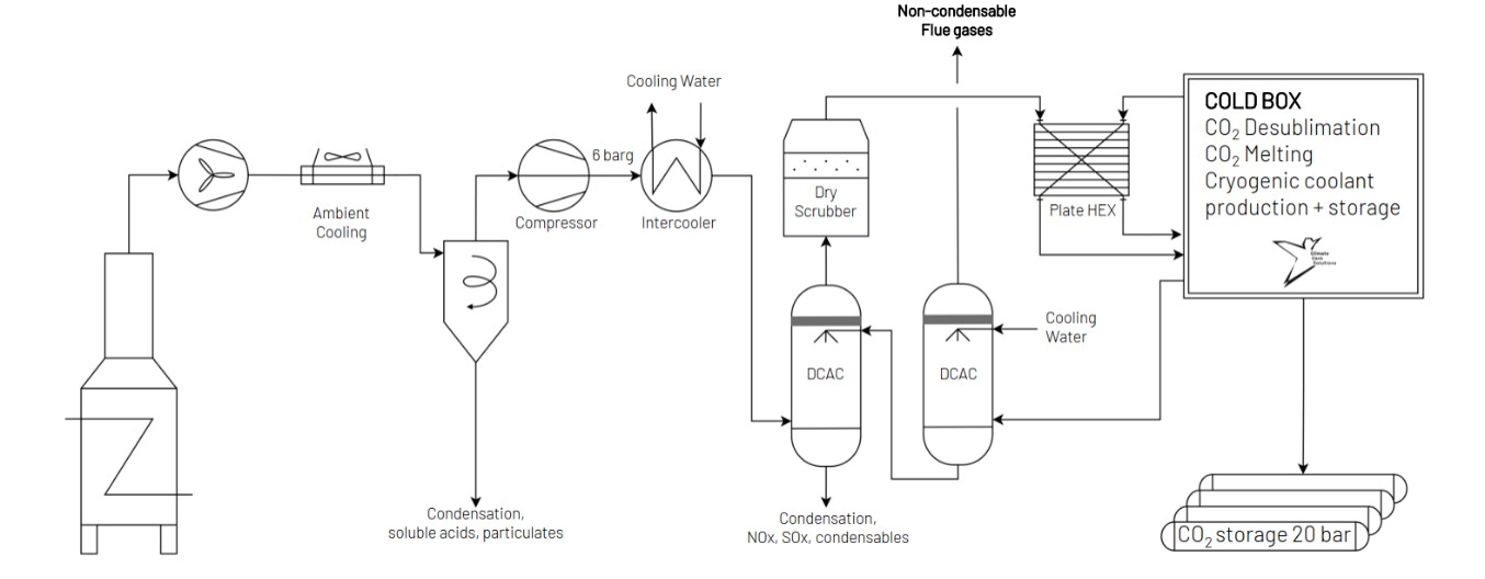
At the core of the Emicap system lies a cryogenic direct contact separator, integrated with a high-performance pretreatment unit. This combination captures CO2 and effectively removes pollutants like SOx and NOx, resulting in pure liquid CO2. The cleaned flue gas is then recycled for coolant production, creating a fully circular, closed-loop carbon capture process. The process involves desublimation of CO2 and then melting of the solid phase to liquid phase in the cold box, as shown in the figure below.
This chemical-free, energy-efficient solution fits effortlessly into existing industrial operations, minimizing disruption while providing a cost-effective path to meet environmental targets. Additionally, Emicap's scalable design ensures that even smaller emitters and companies can benefit from tailored, compact systems that deliver the same environmental and operational advantages at a reduced scale.
TECHNICAL ASPECTS (all % are volume-based)
Point sources: All point sources that fall within the CO2 concentration range, such as power plants (natural gas and coal), oil refineries, process heaters, etc. Typical flue gas flow rates are 10,000 – 100,000 Nm3/h.
CO2 concentration range: 8 – 14%
CO2 capture efficiency: > 99%
CO2 purity: > 99% (CO2 pipeline standards)
Min. feed gas pressure: 7 bar (compression energy included below)
Max. feed gas temperature: 10 °C (achieved using recycled cold energy)
Typical scale: Medium (10 – 150 ktCO2/yr) (scale based on 10% CO2 concentration and 8000 h/yr)
Primary energy source: Electricity
Impurity tolerance: SOx, NOx, particulate matter, and other contaminants, excluding CO. Flue gas pretreatment included.
FUNCTION IN CCU VALUE CHAIN
- Capture high-purity CO2 in liquid form.
- Removes impurities, eliminating the need for separate deNOx and deSOx processes.
- Bolt-on technology.
- Post-treatment polishing may be required to remove remaining NOx and SOx to achieve pipeline specifications.
LIMITATIONS
- Initial capital investment can be high due to the specialized cryogenic processing equipment.
- High compression needs reduce efficiency with variable flue gas flow and low CO2 streams.
- Managing excess heat through valorization or disposal.
ENERGY
- All electricity-based processes.
- Compression uses over two-thirds of the energy.
- Coolant regeneration consumes less than one-third.
- Rest consumed by fans, pumps, and control.
CONSUMABLES
- Process water is used for both cooling and cleaning the flue gas during the capture process, where chemicals may be used for wastewater treatment and management.
- No loss of coolant.
| Parameter | Value |
|---|---|
| Electricity (kWh/tCO2) * | 550 |
| Water (m3/tCO2) * | 0.8 |
| Coolant (kg/tCO2) | No loss |
| Chemicals (wastewater treatment) | -NA- |
| Heat produced (kWh/tCO2) * | 615** |
|
* Based on flue gas of 50,000 Nm3/h and 10 vol.% CO2. * Compression energy included **Heat produced is available at 40-50°C |
|
COSTS
CAPEX: €25/tCO2*
Main CAPEX: compressors, direct contact coolers, dry scrubber, cold box, and plate heat exchanger.
Also includes a refrigeration system, other smaller equipment, and engineering costs.
OPEX: €59/tCO2*
Main OPEX: electricity (~90% of OPEX).
Also includes labor, maintenance, chemicals, cooling, and process water.
CO2 capture cost: €84/tCO2*
Depends on scale, CO2 concentration, etc. It can be reduced further by valorization of waste heat.
*Based on flue gas of 50,000 Nm3/h and 10 vol.% CO2; lifetime = 10 years; electricity price = 100 €/MWh; includes CO2 storage at 20 bar until transport.
CO2 avoidance cost: Not available.
ENVIRONMENTAL
CO2 footprint: 82 kgCO2eq/tCO2
Includes only emissions from electricity. Based on 138 kg-CO2/MWhe in Belgium.
Spatial footprint: 30 m2/tCO2
Based on the flue gas of 50,000 Nm3/h and 10 vol.% CO2. Only for the cold box, the pretreatment spatial footprint is not included. Expected to increase linearly with scale.
Environmental issues: None (complete removal of acid compounds, heavy metals, and organic pollutants such as PFAS).
ENGINEERING
Maturity: Proof-of-concept (TRL 3)
Development timeline:
TRL3 (Q4 2023): Proof-of-concept of crucial equipment ran for multiple hours with a flow rate of 50 Nm3/h.
TRL6 (Q4 2025): Pilot of process for three months on four sites with a flow of 100 Nm3/h. Cold generation is not yet included.
TRL7 (2027): Complete 10.000 Nm3/h flue gas treatment.
Retrofittability: Feasible
Engineered from the outset to function independently and to be retrofitted onto any stack.
Scalability: High (modular)
Designed to handle flow rates up to 100,000 Nm3/h, with scalability for larger volumes.
Process type: Cryogenic without solvents/sorbents and chemical reactions.
Deployment model: Only centralized.
CO2 separation occurs only in the cold box.
Technology flexibility: Hybridizing with other CO2 capture technologies could become feasible if the CO2 concentration is increased upstream.
TECHNOLOGY PROVIDERS
- Cryogenic capture by Emicap, Belgium
Cooperation with technology providers for cold production will be established in the future.
INNOVATIONS
- Captures nearly all CO2 from flue gas as a pure liquid.
- Eliminates all pollutants, including SOx, NOx, and PFAS.
- A purely physical process that avoids the use of chemicals, enhancing safety and reducing operational costs.
- No dangerous chemicals are used for the coolant.
BENCHMARK
Cryocap™ from Air Liquide.
CONTACT INFO
Mohammed Khan (mohammednazeer.khan@vito.be)
Miet Van Dael (miet.vandael@vito.be)
Luigi Meersman (lme@emicap.eu)
ACKNOWLEDGEMENT
This infosheet was prepared as part of the MAP-IT CCU project funded by VLAIO (grant no. HBC.2023.0544).
REFERENCES
Information provided by Emicap.