Synonyms, abbreviations and/or process names
- Baghouse filter
- Tube filter
- Cartridge filter
- Compact filter
- Sleeve filter
Removed components
- Dust, particles
Diagram
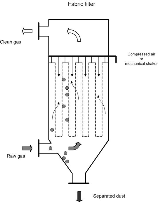
Process description
Filtration
A fabric filter installation consists of a casing which contains a filter medium (the fabric). This filter divides the filter casing into a dirty section and a clean section.
The dirty section, where the dust-laden air enters, is normally the bottom section or the middle section of the casing. The incoming air does not normally flow directly towards the filters, but is passed via one or multiple dispersion plates. The purpose of this is to create a better spread across the filter, whereby it receives a more even load. The air also loses a vast part of its kinetic energy, whereby pre-separation takes place due to gravity.
The air polluted with dust is passed through the fabric filter and is rid of dust particles. The dust is periodically removed from the filter and is collected in a tray under the filter installation (hopper).
Cleaning mechanism
The dust that collects in and around the filter during the filter process must occasionally be removed. The most commonly used systems are:
- Shaking mechanism;
- Reverse air system (reversal of flow direction);
- Compressed air;
- Combination of various systems;
- Ultrasonic cleaning
Cleaning via a shaking mechanism is the oldest used method. This involves the filter fabric being shaken back and forth. Because the fabric filter is subjected to a high mechanical load, this method is rarely used, apart from in very small, discontinuously operating installations.
In reverse air cleaning, the filter is divided into a number of compartments. The outlet in each compartment can be closed off from the rest of the fabric filter, after which a ventilator blows clean air through the filter material in the reverse direction. This rinsing air consists of clean gas. The rinsing air flows inside, through the bag and the dust is left in the filter bag. Due to the low air pressure used in reverse blowing, the filter material is subjected to a relatively low mechanical load during cleaning.
In compressed air cleaning, a short compressed air burst of 0.05 to 0.3 seconds is passed into the filter bag, whereby the filter material suddenly rises. Thus the layer of dust found on the outside of the bag breaks, and falls down into the collection tray. In high pressure cleaning (4 – 8 bar), the compressed air flows through a venturi and, if set-up is effective, takes a huge amount of secondary air with it. This secondary air is essential for effective cleaning. A venturi is not used at low air pressures (1 – 2 bar).
Compressed air cleaning can take place while operation is still on-going. This is why a distinction is made between on-line and off-line cleaning. In off-line cleaning, a filter compartment is first closed-off and is then cleaned. This allows flue gases to fall with greater ease, and prevents them from being hindered by dirty gas.
The advantage of "on-line cleaning is that valves are not required to close a compartment, and that the entire filter surface is used for flue gas filtration.
The cleaning process can be operated via a time switch or a pressure regulator. The disadvantage of a fixed time period at low dust concentrations, is that the filter is cleaned more often than necessary; a pressure regulator is able to resolve this problem.
Fabric materials
Fabric materials can be divided into two groups, namely tissue and felt.
A tissue is a two-dimensional network and can be woven in various ways – which means there is a difference in permeability and pliability. Further, the properties of the tissue are influenced by the characteristics of the thread or fibre, the surface treatment and the coating. The filter qualities of a tissue are greatly determined by the dust-cake which builds up on the filter.
Felts used in flue gas cleaning consist of a grid support-tissue, into which fibres are punched. Due to the three-dimensional network of fibres, the felt becomes effective for filtration purposes. Due to the higher mechanical strength of felt, compared to tissue, high fabric loading is possible, whereby a smaller filter installation is sufficient.
Fabric materials are available in various qualities – the thickness and specific weight are variables.
The basic materials for filter fabrics in flue gas applications are:
- Polyacrylonitril (Dralon-T)
- Aromatic polyamide (Nomex)
- Polytetrafluorethylene (PTFE)
- Glass fibre
- Ryton (fabric material based on polyfenyl and dichlorobenzene)
All these materials have specific advantages and disadvantages in terms of temperature, mechanical strength, chemical resistance and cost aspects, all of which have been summarised in the table below:
|
Filter material |
Dralon-T |
Nomex |
PTFE |
Glass fibre |
|
Max. continuous operating temp. |
130 °C |
200 °C |
260 °C |
220 -280 °C |
|
Moisture resistance |
good |
average |
excellent |
good |
|
Acid resistance |
good |
average |
excellent |
good |
|
Base resistance |
average |
good |
excellent |
average |
|
Mechanical strength |
good |
good |
reasonable |
reasonable |
|
Combustibility |
combustible |
Non combustible, decomposition above 370 °C |
Non-combustible |
Non-combustible |
|
Relative price |
1 |
2.5 – 3.5 |
10 - 15 |
4 – 6 |
Design data
The most important design parameters are:
- Flue gas volume
- Operating and maximum temperature
- Flue gas composition
- The filter-load or filter-ratio: The filter load is the gas throughput per square metre of filter material, with a unit of m³/h per meter square for filter surface. Filter load is determined by the type and nature of the fabric material, dust-load and the type and particle size of dust.
Pressure drop in the filter system is caused by:
- Construction issues related to the filter housing
- The filter medium
- Filter dust-cake
The pressure drop in clean filter mediums is linearly determined by the filter load, the dynamic viscosity and the thickness of the filter medium. The size, construction and shape of the filter medium all play an important role.
In numerous experiments, pressure drop over a non-fouled fibre fabric has shown the following correlation:
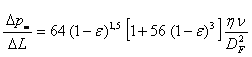
∆pm = pressure drop over the fibre fabric
∆L = thickness of the fibre fabric
Ɛ = porosity of the filter medium
ƞ = dynamic viscosity
ν = filter load
DF = fibre diameter
During dust collection, resistance over the filter medium is increased by the increasing amount of dust-cake. The pressure drop attributable to the dust-cake can be outlined as follows:
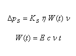
KS = dust-cake resistance
ƞ = dynamic viscosity
W = the mass of separated dust on the filter surface
c = dust concentration
E = separation grade
t = time
The difficulty lies in trying to determine dust-cake resistance KS. Average dust-cake resistance can be experimentally determined by using the above formula, whereby a temporary pressure progress is registered.
Variants
Compact filter
A variation of fabric filters is the compact filter, also referred to as a cartridge filter or envelope filter.
These compact filters come in various sizes and capacities. Standard units are often used, which can be used to construct filter installations with larger capacities.
The difference with fabric filters is the compact construction and the way in which filter elements are introduced to the filter housing. They are assembled in a manner that allows them to be easily replaced.
Low-ratio and high-ratio filters
A distinction can be made between two main types of filter system – low-load (low-ratio) or high-load (high-ratio) filters (see design details). High-load filters have a filter-fabric load of 60-120 m/h, depending on the filter medium, and are suitable for compressed air cleaning:
A few average values for various filter materials:
|
Filter material |
Average filter-fabric Load (m/h) |
|
Glass fibre |
60-120 |
|
Dralon-T |
80-100 |
|
Nomex |
80-100 |
|
Teflon |
80-100 |
Low-load filters have a filter-fabric load of 20-29 m/h and are normally made of a woven filter material.
In medium-sized and large industrial applications, low-ratio filters are being more commonly replaced by high-ratio filters.
However, for the separation of fine dust from large air quantities, as in power plants, low-ratio filters continue to be used. These filters are also referred to as baghouses. In small-scale industrial applications, both types are common, along with a variety of hybrid types. Increases in fabric-load mean that specific application types must be selected, on the basis of cleaning systems and filter mediums.
Catalytic fabrics
For specific applications, catalysts can be incorporated into the fabrics – thus creating catalytic fabrics. Vanadium/titanium are used as catalysts. The most common application is the removal of dioxins and furans, but other pollutants such as VOC, PAK’s, PCB’s and other chlorinated compounds can also be removed.
Efficiency
The removal yield is 99 – 99.9%.
Residual emissions are determined by the used fabrics, but concentrations < 10 mg/Nm³ can be realised.
Boundary conditions
- Flow rate: 300 -1,800,000 Nm3/h
- Temperature: Above dew point and < 135 °C (basic set-up)
- In-coming concentrations: 0.1 -230 g/Nm3
Auxiliary materials
- Filter fabrics: 11 – 17 m2 per 1 000 Nm3/h. The life-span of a fabric is determined by the quality of that fabric and the type of application.
- Compressed air
Environmental aspects
- Dust as residue. The residue quantity is determined by the application type.
- Fabrics once they have been replaced.
Energy use
The energy used by fabric filters is mainly determined by the cleaning system and the filter resistance.
Filters with a high fabric load (high-ratio) and a compressed air system have a higher yield, but also a higher energy usage. Filters with a low fabric load (low-ratio) and a reverse air system or a shaking system, have a lower yield but also relatively low energy usage.
Energy use varies between 0.2 – 2.0 kWh/1 000 Nm³.
Cost aspects
- Investment
- 1 000 – 13 000 EUR depending on the capacity and the set-up of the housing and 500 - 700 EUR for filter material for 1 000 Nm³/h [1, 2, 5, 6]. The proportion of fabric material costs, as a percentage of total investment, can vary from 10% to in excess of 50%. The table below shows the costs for simple systems per m3/h. [5]
|
Capacity in m3/h |
Investment costs (€) |
|
> 100 000 |
1 – 4 |
|
10 000 – 100 000 |
4 – 7 |
|
1 000 – 10 000 |
7 – 13 |
|
< 1 000 |
> 13 |
A few guide prices for the filter material and fastening devices:
|
Filter material |
Guide price (€/m2) |
|
Dralon-T |
15 |
|
Nomex |
60 |
|
PTFE |
80 |
|
Glass fibre |
180 |
- Operating costs
- Personnel costs: ca. 2 mh/week
- Auxiliary and residual materials: 100 to 140 EUR per year for 1 000 Nm³/h. Transport costs for the separated dust are determined by the type of residue.
- Inert: ca. 75 EUR/ton
- Chemical: 150 – 250 EUR/ton
- Operational costs: 0.2 -1.5 EUR per m³/h [5]
Advantages and disadvantages
Advantages
- High removal yield for coarse and fine dust;
- Varying load does not influence pressure drop and efficiency;
- Collected dust can possibly be re-used in the process;
- Residual emissions are determined by incoming concentrations;
- Relatively easy to use.
Disadvantages
- No high moisture level or droplets. Eventual additional heating, of the housing for example, can prevent moisture condensing on the filter. If this is not possible, the fabric filter cannot be applied;
- Risk of explosion; Sparks and soot must be avoided. Sparks must be extinguished before they reach the filter. Soot is susceptible to self-combustion;
- Electrostatic loading possible;
- Sticky dust must be avoided. Eventually, extra auxiliary materials can be added.
Applications
Fabric filters can be employed in many processes and, by using the right filter material, many apparent limitations can be overcome.
This technique also allows acid components to be removed or dioxins to be absorbed – for this, lime and activated carbon, respectively, are injected into the fume channel.
Dioxins can also be removed by using catalytic fabric filters (see variants).
Used in:
- The chemicals industry
- Metal processing industry
- Cattle-feed industry
- Foodstuffs industry
- Waste processing industry
References
- Factsheets on Air-emission reduction techniques, www.infomil.nl, Infomil
- Common waste water and waste gas treatment and management systems in the chemical sector. BREF document, European IPPC Bureau, http://eippcb.jrc.es
- Elslander H., De Fré R., Geuzens P., Wevers M. (1993). Comparative evaluation of possible gas purification systems for the combustion of household waste. In: Energie & Milieu, 9
- Vanderreydt I. (2001). Inventory of the waste incineration sector in Flanders, Vito, 2001/MIM/R/030
- Work-book on environmental measures: Metal and electro-technical industry (1998 ). VNG publishers
- Supplier information
- VDI 3677, Filternde abscheider, Oberflächenfilter