Synonyms, abbreviations and/or process names
- Dry E-filter
- Dry ESP
- Dry Electrostatic Precipitator
Removed components
- Dust, particles, aerosols
Diagram
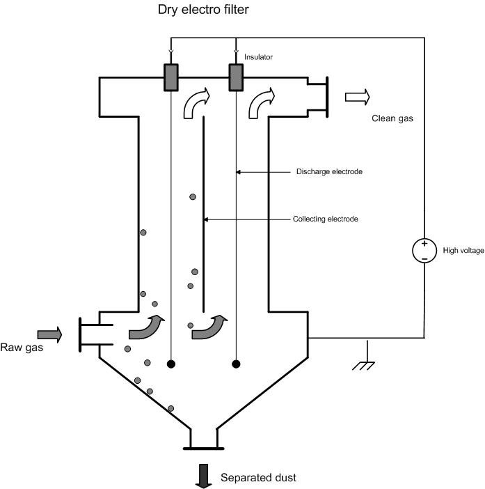
Process description
Working principle
Solid or liquid particles in a gas stream are negatively loaded in an electric field caused by discharge electrodes. Under the effect of the electric field, they are then removed out of the gas stream. The already separated particles can be collected on positively loaded collection electrodes or collectors. Disposal of separated particles (liquid) takes place via gravity or, as in the case with solids, by periodically knocking or vibrating the collection electrodes, whereby the build-up falls in flakes or blocks from the collection electrodes into a tray – the so-called ‘bunker’.
Though in principle, when using a dry electro filter, it is possible to collect aerosols on the collector-electrode; though when cleaned, they do not go into the bunker but stay in the air phase as aerosols do not sink.
Construction aspects
An electro filter consists of one or more chambers, over which the gas input is divided. Well dispersed gas, via a gas dispersion screen, must lead to an even distribution of dust over the various chambers. Dead spaces must be kept to a minimum in order to prevent leakage of unclean gas. In addition to parallel distribution, an electro filter also consists of a number of fields in series. These fields work independently of each other. The first field removes most of the dust and the latter fields, though collecting little dust, help to keep residual emissions to a minimum by collecting ‘difficult’ fly ash. A number of independently adjustable fields should have preference, due to residual emissions and operating certainty. Each of these fields is fitted with a separate dust tray.
Another important construction aspect is the way in which electrodes are cleaned.
One can knock on the centre of an electrode plate or on top of it. The downside of the latter approach is that part of the separated fly ash returns to the gas stream.
The first approach is carried out by striking a hammer against the edge of the plate. The dust then loosens in chunks and slides down the electrode towards the dust tray. If too many plates are cleaned at the same time, residual emission will temporarily rise - thus it is advised to limit the number of electrodes that are knocked simultaneously.
Further, plates need to be cleaned regularly. If cleaning does not take place regularly, the layer of fly ash becomes too thick and leads to a drop in efficiency. If cleaning takes place too often, the fly ash does not have the opportunity to bond, breaks into pieces and returns to the gas stream. In this case, plate configuration is important – whereby zones with low gas speed and the height/width relationship of plates heavily determine yield quality.
Design data
The yield of an electro filter, for a non-uniform particle size, is described using an empirical modification of the Deutsch comparison.
![]()
µk = migration speed (m/s);
A = total precipitation surface (m2);
Q = actual gas throughput (m3/s);
k = empirical constant.
The Deutsch comparison shows that electro filter size required is determined by the collection yield and the migration speed.
Because collection yield is directly determined by dust inflow and outflow concentrations, the acceptable residual emission is an important design criterion for determining the required filter surface area.
The migration speed is the speed with which the particle moves towards the precipitation electrode. The migration speed is partly determined by the properties of the dust (specific resistance) and flue gas. The specific resistance of dust is also determined by the temperature. On the other hand, migration is also influenced by a number of the electro filter’s design and construction aspects, including corona-tension, field strength and electrode profiles.
The specific precipitation surface is defined as the quotient of the precipitation-electrode surface and the gas flow volume.
The gas speed through the electro filter establishes the residence time for a specific precipitation surface. In practice, one implements gas speeds of 1 to 2m/s.
Variants
The two-stage electro filter is made up of two compartments, where ionisation takes place in the first one and the particles are collected in the second one.
Efficiency
For total dust-removal the efficiency is > 99%. The removal yield for particle sizes ? 10 µm lies between 97 and 99 % and between 96 and 99 % for particles ? 2,5 µm.
Residual emissions: 5 -50 mg/Nm3
Boundary conditions
- Flow rate: 1 800 -1 800 000 Nm3/h
- Temperature: 700 °C
- In-coming concentrations: 1 -110 g/Nm3
Auxiliary materials
None
Environmental aspects
Collected dust as residue
Energy use
Energy use varies between 0.17 – 0.35 kWh per 1 000 Nm3 depending on installation type. Further, usage of 0.17 – 0.5 kWh must be accounted for the ventilator.
Cost aspects
- Investment
- Operating costs
- Personnel costs: ca. 0.25 mh/day (electrode maintenance)
- Auxiliary and residual materials: Processing cost for the separated dust is determined by the type of residue.
- Inert: ca. 75 EUR/ton
- Chemical: 150 – 250 EUR/ton
- Operational costs: 0.05 – 0.1 EUR per 1 000 Nm³/h for systems greater than 50 000 m3
Advantages and disadvantages
Advantages
- Very high collection yield realised, higher than 99%.
- It is possible to effectively collect small particles using an electro filter There is no theoretical restriction on particle size.
- Dust can normally be separated dry, which offers the opportunity to re-use separated matter.
- Electro filters are suitable for dealing with very large gas streams, while high temperatures can also be accommodated.
- By using special materials, it is possible to make the electro filter suitable for corrosive gas streams.
- The yield of an electro filter can be later increased by constructing multiple fields or zones.
- Low pressure drops 0.05 – 0.3 kPa
Disadvantages
- In general, electro filters are less suited to processes with variable operating conditions, i.e. varying dust concentrations. Though this downside can be partially remedied via automatic voltage regulation. Variable operating conditions do not present problems if the installation has been designed for the most severe set of conditions.
- They are less suited to the removal of dust with high or very low electrical resistance;
- It is difficult to remove particles with a surface size that is large compared to the mass, because they start to travel with the turbulent gas stream once again;
- For difficult-to-separate substances, the size of the to-be-treated gas stream and the required yield, may lead to space problems.
- Maintenance-sensitive;
- Risk of explosion for flammable dust (e.g. soot)
Applications
The most common application areas are energy plants and waste incineration installations.
In the case of coal power plants, reference is often made to easy’ and difficult coals. This relates to the specific resistance of the flue gas, which is partly determined by the chemical composition of the flue gas. Coals are also characterised as follows:
|
Composition and content |
||
|
|
Easy coals |
Difficult coals |
|
Fe2O3 |
high |
low |
|
Na2O |
high |
low |
|
CaO |
low |
high |
|
MgO |
low |
high |
Further, flue gas composition is also relevant, namely the SO3 and moisture contents. In low SO3-concentrations the resistance is greater than in high SO3 levels.
SO3 can originate from sulphur found in coal, but can also be artificially added to the flue gas – this process is called conditioning. Water (steam), ammonia and triethylamine are used as conditioning products.
Considering that specific resistance is also determined by temperature, flue gas resistance is at its highest at a temperature of 150 to 200°C. This range is avoided when E-filters are designed.
References
- Factsheets on Air-emission reduction techniques, www.infomil.nl, Infomil
- Common waste water and waste gas treatment and management systems in the chemical sector. BREF document, European IPPC Bureau, http://eippcb.jrc.es
- Elslander H., De Fré R., Geuzens P., Wevers M. (1993). Comparative evaluation of possible gas purification systems for the combustion of household waste. In: Energie & Milieu, 9
- Vanderreydt I. (2001). Inventory of the waste incineration sector in Flanders. Vito, 2001/MIM/R/030
- Work-book on environmental measures: Metal and electro-technical industry (1998 ) VNG publishers
- Supplier information
- Jacobs A., Gielen B., Van Tomme, De Roock Ch. and Dijkmans R., Best Available Techniques for the wood-processing industry, 2003
µk = migration speed (m/s);
A = total precipitation surface (m2);
Q = actual gas throughput (m3/s);
k = empirical constant.
The Deutsch comparison shows that electro filter size required is determined by the collection yield and the migration speed.
Because collection yield is directly determined by dust inflow and outflow concentrations, the acceptable residual emission is an important design criterion for determining the required filter surface area.
The migration speed is the speed with which the particle moves towards the precipitation electrode. The migration speed is partly determined by the properties of the dust (specific resistance) and flue gas. The specific resistance of dust is also determined by the temperature. On the other hand, migration is also influenced by a number of the electro filter’s design and construction aspects, including corona-tension, field strength and electrode profiles.
The specific precipitation surface is defined as the quotient of the precipitation-electrode surface and the gas flow volume.
The gas speed through the electro filter establishes the residence time for a specific precipitation surface. In practice, one implements gas speeds of 1 to 2m/s.
Variants
The two-stage electro filter is made up of two compartments, where ionisation takes place in the first one and the particles are collected in the second one.
Efficiency
For total dust-removal the efficiency is > 99%. The removal yield for particle sizes ? 10 µm lies between 97 and 99 % and between 96 and 99 % for particles ? 2,5 µm.
Residual emissions: 5 -50 mg/Nm3
Boundary conditions
<!--[if !supportLists]-->- <!--[endif]-->Flow rate: 1 800 -1 800 000 Nm3/h
<!--[if !supportLists]-->- <!--[endif]-->Temperature: ? 700 °C
<!--[if !supportLists]-->- <!--[endif]-->In-coming concentrations: 1 -110 g/Nm3
Auxiliary materials
None
Environmental aspects
Collected dust as residue
Energy use
Energy use varies between 0.17 – 0.35 kWh per 1 000 Nm3 depending on installation type. Further, usage of 0.17 – 0.5 kWh must be accounted for the ventilator.
Cost aspects
<!--[if !supportLists]-->q <!--[endif]-->Investment
<!--[if !supportLists]-->- <!--[endif]-->Costs 10 to 20 EUR per m³ for systems from 30 000 – 200 000 m3/h [1, 2, 6]
<!--[if !supportLists]-->- <!--[endif]-->An installation of 60 000 Nm3/h costs ca. 1.8 million EUR, for other flow volumes use a scale-up factor of 0.6 [7].
<!--[if !supportLists]-->q <!--[endif]-->Operating costs
<!--[if !supportLists]-->- <!--[endif]-->Personnel costs: ca. 0.25 mh/day (electrode maintenance)
<!--[if !supportLists]-->- <!--[endif]-->Auxiliary and residual materials: Processing cost for the separated dust is determined by the type of residue.
Inert: ca. 75 EUR/ton
Chemical: 150 – 250 EUR/ton
<!--[if !supportLists]-->- <!--[endif]-->Operational costs: 0.05 – 0.1 EUR per 1 000 Nm³/h for systems greater than 50 000 m3
Advantages and disadvantages
<!--[if !supportLists]-->q <!--[endif]-->Advantages
<!--[if !supportLists]-->- <!--[endif]-->Very high collection yield realised, higher than 99%.
<!--[if !supportLists]-->- <!--[endif]-->It is possible to effectively collect small particles using an electro filter There is no theoretical restriction on particle size.
<!--[if !supportLists]-->- <!--[endif]-->Dust can normally be separated dry, which offers the opportunity to re-use separated matter.
<!--[if !supportLists]-->- <!--[endif]-->Electro filters are suitable for dealing with very large gas streams, while high temperatures can also be accommodated.
<!--[if !supportLists]-->- <!--[endif]-->By using special materials, it is possible to make the electro filter suitable for corrosive gas streams.
<!--[if !supportLists]-->- <!--[endif]-->The yield of an electro filter can be later increased by constructing multiple fields or zones.
<!--[if !supportLists]-->- <!--[endif]-->Low pressure drops 0.05 – 0.3 kPa
<!--[if !supportLists]-->q <!--[endif]-->Disadvantages
<!--[if !supportLists]-->- <!--[endif]-->In general, electro filters are less suited to processes with variable operating conditions, i.e. varying dust concentrations. Though this downside can be partially remedied via automatic voltage regulation. Variable operating conditions do not present problems if the installation has been designed for the most severe set of conditions.
<!--[if !supportLists]-->- <!--[endif]-->They are less suited to the removal of dust with high or very low electrical resistance;
<!--[if !supportLists]-->- <!--[endif]-->It is difficult to remove particles with a surface size that is large compared to the mass, because they start to travel with the turbulent gas stream once again;
<!--[if !supportLists]-->- <!--[endif]-->For difficult-to-separate substances, the size of the to-be-treated gas stream and the required yield, may lead to space problems.
<!--[if !supportLists]-->- <!--[endif]-->Maintenance-sensitive;
<!--[if !supportLists]-->- <!--[endif]-->Risk of explosion for flammable dust (e.g. soot)
Applications
The most common application areas are energy plants and waste incineration installations.
In the case of coal power plants, reference is often made to easy’ and difficult coals. This relates to the specific resistance of the flue gas, which is partly determined by the chemical composition of the flue gas. Coals are also characterised as follows:
|
Composition and content |
||
|
|
Easy coals |
Difficult coals |
|
Fe2O3 |
high |
low |
|
Na2O |
high |
low |
|
CaO |
low |
high |
|
MgO |
low |
high |
Further, flue gas composition is also relevant, namely the SO3 and moisture contents. In low SO3-concentrations the resistance is greater than in high SO3 levels.
SO3 can originate from sulphur found in coal, but can also be artificially added to the flue gas – this process is called conditioning. Water (steam), ammonia and triethylamine are used as conditioning products.
Considering that specific resistance is also determined by temperature, flue gas resistance is at its highest at a temperature of 150 to 200°C. This range is avoided when E-filters are designed.
References
- Factsheets on Air-emission reduction techniques, www.infomil.nl, Infomil
- Common waste water and waste gas treatment and management systems in the chemical sector. BREF document, European IPPC Bureau, http://eippcb.jrc.es
- Elslander H., De Fré R., Geuzens P., Wevers M. (1993). Comparative evaluation of possible gas purification systems for the combustion of household waste. In: Energie & Milieu, 9
- Vanderreydt I. (2001). Inventory of the waste incineration sector in Flanders. Vito, 2001/MIM/R/030
- Work-book on environmental measures: Metal and electro-technical industry (1998 ) VNG publishers
- Supplier information
- Jacobs A., Gielen B., Van Tomme, De Roock Ch. and Dijkmans R., Best Available Techniques for the wood-processing industry, 2003