Synonyms, abbreviations and/or process names
- Cooled condensation
Removed components
- Solvents
- VOC
Diagram
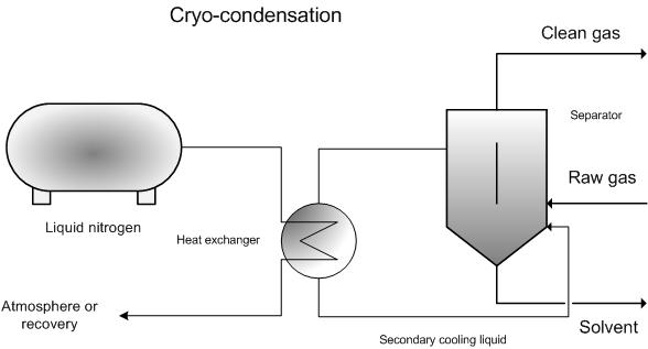
Process description
Cryogenic condensation is normally performed as indirect condensation. The cooling medium is separated from to-be-treated gases by a heat exchanging surface.
In cryogenic solvent removal, the aim is to re-use the condensed solvent.
To improve the separation of solvents, a number of points need to be addressed:
Sufficient residence time and a turbulent stream in order to cool all the gas.
- The condenser temperature must be low enough and the cooling capacity must be high enough.
- The air quantity in the organic fraction must be minimised. This air leads to higher energy use and a higher level of solvents that cannot be separated (lower yield). In order to limit the air volume, absorption can be implemented whereby a more concentrated desorption stream can be treated in the condenser. This leads to greatly-reduced cooling capacity and an improved separation efficiency in the condenser.
- For the condenser, it is best to select a temperature below the freezing point of the solvent so that there will be minimal vapour pressure from the solvent.
- The solvents must then be periodically removed from the condenser surface.
When selecting the type of material, one must bear in mind corrosion suffered by heat exchangers. Typical cooling elements are made of copper and aluminium. Further, the cooling element can also be made of stainless steel. Stainless steel normally experiences few corrosion problems. In cryogenic condensation, stainless steel is recommended because it does not normally display signs of brittleness and has no compatibility issues with organic substances. If carbon steel is used, extra attention must be paid to corrosion, reaction with organic components and brittleness if the temperature lies below the metal’s transition point. In the case of brine coolers, particular attention needs to be paid to corrosion because the solution contains NaCl, CaCl2 and KCl. In this case, one must select appropriate materials.
If the residual concentration of solvents, after the condenser, is too high for discharge into the atmosphere, then the flue gases must be treated further. This can be done by applying absorption techniques, biological techniques, non-thermal oxidation….
Variants
Cooling medium
The cooling medium determines the lowest operating temperature. The residual solvent concentration is determined by the temperature and decreases (logarithmically) when temperature decreases. For specific solvent compositions, a specific residual concentration can be realised by selecting the right condensation temperature.
The following temperature levels can be realised [1]:
- Ammonia: -40 °C for one stage and -60 °C for two stages
- CFK’s: -53 °C;
- Muti-stage CFK installations down to -73 °C, but these are less efficient
- Reverse Brayton cycle: -73 °C
- Liquid nitrogen: down to -195 °C
In practice, cooling rarely occurs below -95 °C and the condensation temperature lies between -40 and -80 °C.
Liquid nitrogen is often used for small (batch) systems because they are on stand-by for large periods of time. Larger continuous systems (> 250 m³/h) are less frequent.
For large flow rates (> 1 000 m³/h) the condensation temperature is normally -30 °C or higher and practical residual emissions lie between 1 and 5 g/Nm³. Residual emissions must then be treated using another technique.
Direct implementation of nitrogen
It is possible to introduce liquid nitrogen directly into the gas stream. The solvents will freeze in the air and produce solvent snow. This is then separated via filtration. The solvent is recuperated by allowing it to defrost.
Efficiency
Efficiency is determined by the components and the condensation temperature. A few examples [3].
|
Component |
Condenser temperature (°C) |
End concentration (mg/Nm³) |
|
Acetone |
-86 |
< 150 |
|
Dichloromethane |
-95 |
< 20 |
|
MEK |
-75 |
< 150 |
|
Methanol |
-60 |
< 150 |
|
Toluene |
-65 |
< 100 |
Efficiency can also be improved by compacting to-be-treated gas. As a result of the compression, the vapour pressure of the to-be-treated component increases proportionately. For example, increasing the pressure from 1 bar to 5 bar increases the vapour pressure by a factor of 5. If the condensation temperature is reached at 1 bar, 80% of the components will condense after compression. This can be used to increase the required condensation temperature.
For start concentrations of 5 g/m³, removal percentages between 50 - 90 % can be realised via compression cooling systems. When using cryogenic systems, yields between 95 - 99.9% can be realised [1].
With a flow rate of 1 000 m³/h and a VOC concentration of 200 – 1 000 g/Nm³, end concentrations between 1 – 5 g/Nm³ are possible. If necessary, adsorption needs to be implemented later in the process (see activated carbon adsorption, zeolite adsorption, polymer adsorption and regenerative sorption)
Boundary conditions
- The flow rate must be low enough to limit the required cooling capacities. In the case of cryogenic condensation, certainly < 5 000 m³/h [1]. Most applications have a flow rate < 250 m³/h [1]
- Gas temperature < 80 °C
- Pressure between 20 mbar and 6 bar [3]
- Incoming solvent concentrations must be high: 20 – 1 000 g/Nm³ [3]
: > 5 g/Nm³ [5]
- For wet gas streams, measures must be taken to limit ice-forming in the condenser by introducing a prior dehumidification phase.
Auxiliary materials
A nitrogen supply is needed for cooling with liquid nitrogen. If a cooling circuit is used, only a suppletion cooling medium is needed.
An estimated 10 kg/h of liquid nitrogen is needed for every kW of required cooling. However, this is also determined by the design of the installation and the type of solvent [1].
In optimal circumstances, the vaporised nitrogen can be used in the process for inertisation, for example. If liquid nitrogen has already been supplied for these applications, there will be no extra usage.
Environmental aspects
Residual emissions must be further treated.
Solvent recuperation if the solvent is re-used.
If the separated solvent is impure, it may be too expensive to upgrade it to a reusable product – thus destruction (incineration) would be recommended.
Energy use
Determined by the employed technique. Energy use can be limited by using multi-stage cooling, whereby air is cooled at suitable temperatures, with the optimum cooling medium being used each time. There is a trade-off between investment costs and operating costs.
Energy use is primarily determined by the required cooling capacity, the cooling temperature (the lower, the more energy-intensive) and the type of cooling.
Cost aspects
- Investment
- Operating costs
Case study CS2 removal [6]
- Maximum flow rate: 500 Nm³/h
- Maximum concentration CS2 = 124 g/Nm³
- Maximum flow rate: 500 Nm³/h
- Condenser temperature: -120 °C
- Investment costs: 360 000 EUR for a liquid nitrogen condenser
- Liquid nitrogen costs: 24 000 EUR/year
Advantages and disadvantages
Advantages
- Compact technology
- Recuperation of organic solvents if pure solvents can be separated
- Desired end concentration can be selected by selecting the right condenser temperature
- High efficiency for high VOC concentrations
Disadvantages
- Use of liquid nitrogen, which must be produced or purchased
- For wet gas streams, measures must be taken to limit ice-forming in the condenser by introducing a prior dehumidification phase.
Applications
Cryogenic condensers are used for:
- Process gases from reactors
- Gases derived from storage tanks (particularly during filling)
- Small gas flows with high VOC concentrations
References
- EPA technical bulletin: Refrigerated condensers for control of organic air emissions December 2001
- BREF: "Common waste water and waste gas treatment /management systems in the chemical sector" EIPPC, February 2002
- Factsheets on Air-emission reduction techniques, www.infomil.nl, Infomil
- J.C.Mycock, et Al.:" Air pollution control engineering and technology" Lewis publishers, 1995
- Solvent capture for recovery and re-use from solvent laden gas streams, Environmental Technology Best Practice programme, guide GG 12
- Supplier information
- A. Jacobs, B. Gielen, I. Van Tomme, Ch. De Roock and R. Dijkmans., Best Available Techniques for the wood processing industry, October 2003